
STE SMD NTC Thermistors Featured in Fast Charging Supplier Roundup
Original report
STE edition
A four-supplier survey of surface-mount NTC thermistors from Jiankun, JingQin, STE and TRX, covering packages, reported electrical ranges, assembly and application examples.
Chongdiantou included STE in a July 28, 2025 survey of surface mount NTC thermistors for compact, high-power-density chargers. The original article also covered Jiankun, JingQin and TRX, presenting the companies in alphabetical order rather than as a performance ranking.
This English edition covers all four suppliers and retains the source’s product distinctions and application references. The translated source tables accompany the narrative; supplier-specific examples remain assigned to their original manufacturer.
Surface mounting as a product direction
The survey described manufacturers moving from conventional leaded thermistors toward packages suitable for surface mount assembly. For charger designers, component height, footprint and assembly method can all become constraints as the enclosure becomes smaller.
NTC means negative temperature coefficient: resistance decreases as temperature rises. The source also distinguishes PTC thermistors, whose resistance rises with temperature, and CTR devices, whose resistance drops sharply over a particular temperature interval. The original article discussed temperature sensing, compensation and inrush suppression across the wider thermistor category. STE's documented 2522 and 3225 products are power NTCs, so their use requires attention to current, self-heating and startup stress in addition to resistance.
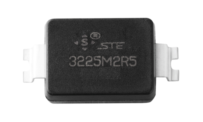
Chongdiantou highlighted STE's 1815, 2522 and 3225 outlines, inward lead forms and molding material described as meeting UL94 V-0. It gave nominal plan dimensions of 4.5 × 3.9 mm, approximately 6.0 × 5.6 mm and 8.1 × 6.0 mm, respectively. These identifiers describe different STE packages; their digits should not be interpreted as generic metric chip dimensions.
STE specifications clarify the reported range
The roundup described an overall STE resistance range of 1.5–200 Ω and B values of 2500–3400 K. The available formal tables provide a more specific basis for evaluating two of the families:
| Documented item | 2522 power NTC | 3225 power NTC |
|---|---|---|
| Reviewed footer revision | 2025-03-21 | 2024-01-17 |
| Resistance range at 25°C | 2.5–200 Ω | 1.5–200 Ω |
| B values appearing in the table | 2600–3200 K, ±10% | 2600–3200 K, ±10% |
| Example 5 Ω maximum steady current | 3 A at 25°C | 4 A at 25°C |
| Operating temperature range | −40 to +175°C | −40 to +175°C |
These values come from page 5 of each specification. The wider ranges in the historical survey are not treated as additional formally specified options. The B-value calculation interval also needs confirmation before using the value in a numerical temperature model.
The formal 2522 body drawing is 6.0 ±0.1 × 5.55 ±0.1 × 2.38 ±0.1 mm. The 3225 drawing gives 8.1 ±0.3 × 6.0 ±0.3 × 2.5 ±0.3 mm. Both the tolerance and termination drawing matter when comparing the packages with available board space. A formal specification for the reported 1815 power NTC has not been verified for this adaptation.
Application claims need the circuit conditions
The STE section named industrial control, communications, consumer and automotive electronics as potential application areas. It also referred to lightning-related stress tolerance. These statements describe the report's positioning; they do not establish automotive qualification or a complete surge-protection result for every variant.
For power-up current limiting, the selected NTC must accommodate both the initial charging event and steady operation. The formal specifications include temperature derating, so the 25°C current entry cannot be carried unchanged into a hotter enclosure. Restart behaviour matters as well because the component may remain warm after a short interruption.
Surface mount packaging provides an assembly option for those requirements. Its presence in a supplier survey is useful product context, while selection still needs the exact resistance, current conditions, startup energy and mounting arrangement. The specific formal tables give engineers a clearer starting point than a single portfolio-wide range.
Jiankun: 4524 and 2822 power NTCs
The Jiankun section describes compact 4524 and 2822 packages, both with a zero-power resistance range of 1.5–20 Ω. It emphasizes inrush-current suppression, resistance to humidity and temperature cycling, and a thermally conductive molding material. The source positions the devices for LED circuit protection, industrial and communications equipment, automotive electronics and small household appliances.
Reel supply and compatibility with lead-free reflow and wave-soldering processes are presented as manufacturing features. The article prints the material classification as “UL94-V05”; that string is ambiguous and is not converted here into a verified flammability classification. It also reports CQC, UL and TUV approvals for related Jiankun products without identifying the complete certificate scope for each NTC. The source heading spells the brand JK-EK, while its company listing uses JK-ET; this edition uses Jiankun consistently.
JingQin: two temperature ranges
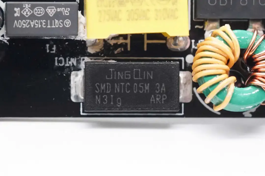
JingQin's section likewise describes 4524 and 2822 surface-mount NTC packages, covering 1.5–20 Ω zero-power resistance and B values of 2500–3200 K. It assigns operating ranges of −40 to +175°C to 4524 and −40 to +200°C to 2822. These are the survey's product descriptions; the B-value measurement interval and exact electrical options remain part-specific.
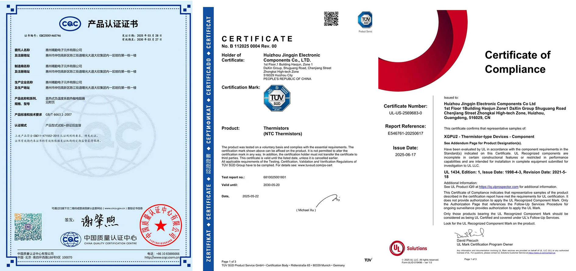
The report highlights UL94 V-0 molding material, compact construction and fast response, together with humidity, high-temperature and inrush-current performance. Named applications include LED protection, industrial and communications equipment, consumer products and automotive electronics. Its CQC, UL and TUV statements describe reported product approvals, rather than independent verification of all variants.
The accompanying application list points to five published teardowns: a Mcdodo 70 W 2A2C six-in-one GaN power strip, a UGREEN 65 W 2C1A slim GaN charger, GOSIRY 45 W and 60 W dual-USB-C GaN chargers, and a Xiaomi 90 W Xiaobuding GaN charger. These are JingQin references in the source and are not STE applications. The related-reading link discusses JingQin's shipment of SMD thermistors.
TRX: horizontal assembly and two package sizes
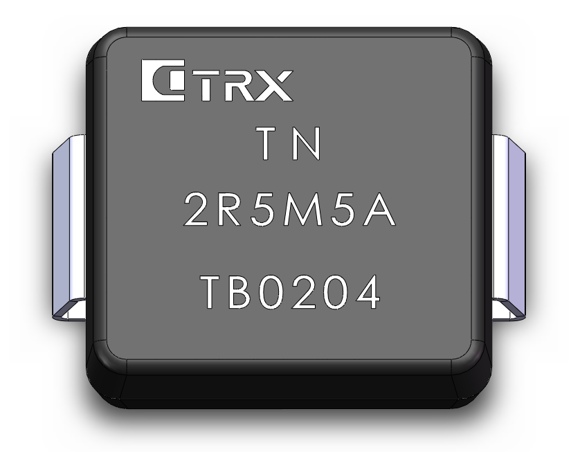
TRX describes a horizontally assembled thermistor element with two soldered terminations for SMT placement. Molded packaging is intended to control the external dimensions, while the source highlights low weight, vibration resistance, sensitivity and reduced solder-joint defects. Those comparative manufacturing claims are presented without a controlled production study.
The reported 6056 package measures 6.0 × 5.6 × 2.2 mm; 10596 measures 10.5 × 9.6 × 2.58 mm. Both are described with a −40 to +155°C operating range. The source gives a combined zero-power resistance range of 1.5–10 Ω and B values of 2500–2800 K. The translated product tables retain individual selections and conditions.
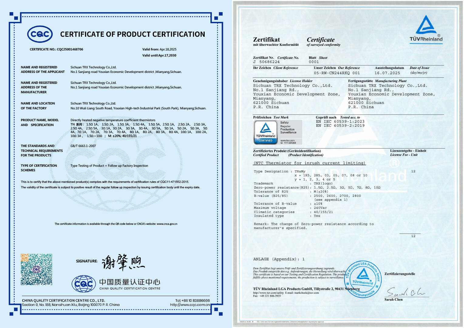
The article positions these parts for circuit protection, industrial and communications equipment and consumer electronics, and reports CQC and TUV approvals for TRX products. Its related-reading link introduces the SMD-NTC family. As with the other suppliers, these statements do not establish the qualification of an unspecified part.
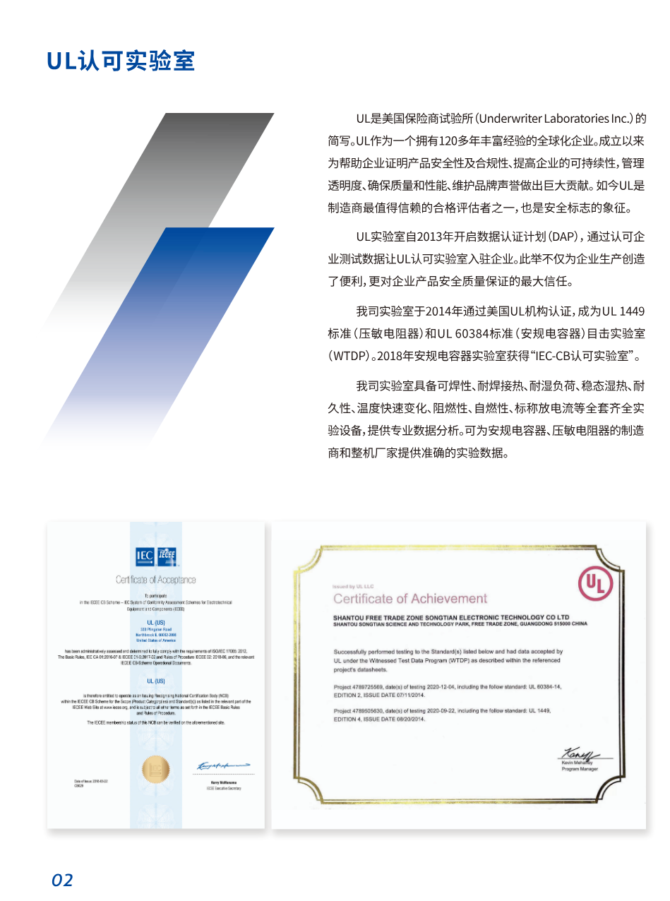
The source also reports that STE’s laboratory became a UL WTDP witness-testing laboratory for UL 1449 varistors and UL 60384 safety capacitors in 2014, with IEC-CB laboratory recognition for safety capacitors in 2018. These historical laboratory statements are separate from approval of an NTC part. The roundup concludes that surface mounting can reduce assembly space and support automated production; the scale of any reliability or cost improvement depends on the component and equipment design. Its further reading includes a three-supplier survey of surface-mount Y capacitors.
Figures and tables from the original report
The following figures retain their original captions, markings and historical context. Transcribed tables present the values shown in the published images; product selection should use the specifications for the selected part.
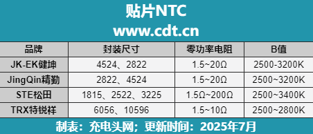
| Brand | Package sizes | Zero-power resistance | B value |
|---|---|---|---|
| JK-EK (Jiankun) | 4524, 2822 | 1.5–20 Ω | 2500–3200 K |
| JingQin | 2822, 4524 | 1.5–20 Ω | 2500–3200 K |
| STE (Songtian) | 1815, 2522, 3225 | 1.5–200 Ω | 2500–3400 K |
| TRX | 6056, 10596 | 1.5–10 Ω | 2500–2800 K |
The source spelling and ranges are retained. JK-EK differs from the JK-ET marking in the following source image. Aggregate ranges do not mean every package supports every listed value.
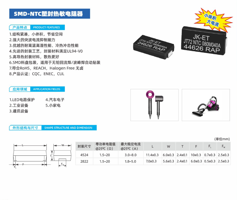
| Package | Zero-power resistance at 25°C (Ω) | Maximum steady-state current at 25°C (A) | L (mm) | W (mm) | T (mm) | F (mm) | FL (mm) | FW (mm) |
|---|---|---|---|---|---|---|---|---|
| 4524 | 1.5~20 | 3.0~8.0 | 11.4±0.3 | 6.0±0.3 | 2.4±0.1 | 10±0.3 | 0.7±0.3 | 2.5±0.3 |
| 2822 | 1.5~20 | 1.8~5.0 | 7.0±0.3 | 5.6±0.3 | 2.4±0.1 | 6.0±0.3 | 0.5±0.3 | 2.5±0.3 |
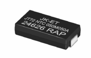
The source product marking reads JK-ET, differing from JK-EK in the roundup table.
| No. | Code / field | Meaning |
|---|---|---|
| ① | SMD | Molded surface-mount package |
| ② | NTC | Power thermistor for inrush-current limiting |
| ③ | Zero-power resistance at 25°C (R25) | 0R5: 0.5 Ω; 2R5: 2.5 Ω; 05: 5 Ω; 10: 10 Ω; 20: 20 Ω |
| ④ | M | Zero-power resistance tolerance: ±20% |
| ⑤ | Maximum steady-state current | X7A: 0.7 A; 1X8A: 1.8 A; 2X5A: 2.5 A; 5A: 5 A |
| Field | Source description |
|---|---|
| Mounting type | SMD |
| Component type | NTC: negative-temperature-coefficient thermistor |
| Approximate body dimensions | 3225≈8.1×6.0 mm;2522≈6.0×5.6 mm;1815≈4.5×3.9 mm |
| Terminal form | N: inward |
| Zero-power resistance codes | 1R5:1.5 Ω;100:10 Ω;101:100 Ω |
| Maximum steady-state current codes | 01:1 A;S5:1.5 A;02:2 A;03:3 A;04:4 A;05:5 A |
| Zero-power resistance tolerance | L: ±15%; M: ±20% |
Approximate dimensions do not replace the detailed dimensional tables.
| Item | Value / expression |
|---|---|
| Ambient temperature Ta | 60°C |
| Illustrative upper temperature Tu | 200°C |
| Source formula | ITa = [1 − (Ta − 25)/(Tu − 25)] × Imax = 80% Imax |
200°C is an illustrative calculation input, not a rated operating temperature for these parts. The accompanying tables specify upper limits of 155°C or 175°C. The source curve is not used to infer additional ratings.
| Item | Source statement |
|---|---|
| Source feature 1 | Molded package; the source states that the encapsulation material meets UL94-V0. |
| Source feature 2 | Compact package intended to save board space. |
| Source feature 3 | The source describes resistance to high temperature and humidity. |
| Source feature 4 | The source describes inrush-current limiting capability. |
| Source feature 5 | Reel packaging for automated assembly using lead-free reflow or wave soldering. |
| Applications listed by the source | Circuit protection, industrial equipment, communications equipment, consumer electronics and automotive electronics. |
These are statements in the historical source image, not independent verification of certification, environmental testing or automotive qualification. Check the specific device soldering profile before assembly.
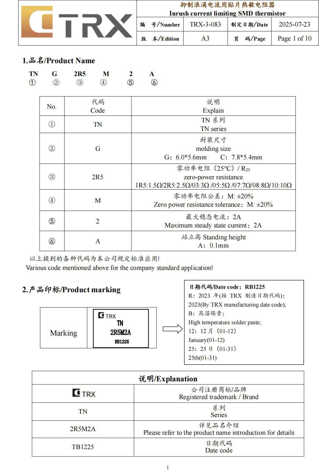
| Field | Value |
|---|---|
| Document number | TRX-3-083 |
| Date | 2025-07-23 |
| Edition | A3 |
| Page | Page 1 of 10 |
| No. | Code | Meaning |
|---|---|---|
| ① | TN | TN series |
| ② | G | Molded body size: G: 6.0×5.6 mm; C: 7.8×5.4 mm |
| ③ | 2R5 | Zero-power resistance at 25°C, R25: 1R5: 1.5 Ω; 2R5: 2.5 Ω; 03: 3 Ω; 05: 5 Ω; 07: 7 Ω; 08: 8 Ω; 10: 10 Ω |
| ④ | M | Zero-power resistance tolerance: ±20% |
| ⑤ | 2 | Maximum steady-state current: 2 A |
| ⑥ | A | Stand-off height: 0.1 mm |
The source states that these codes are the manufacturer’s standard application codes.
| Marking / code | Meaning |
|---|---|
| TRX | Registered trademark / brand |
| TN | Series |
| 2R5M2A | See part-name fields |
| TB1225 | Date code in the lower source table |
| RB1225 | Date-code example in the source marking and explanation box |
| R | 2023 |
| B | High-temperature solder paste |
| 12 | December (01–12) |
| 25 | Day 25 (01–31) |
The source differs between RB1225 in the example and TB1225 in the lower table. Its English text incorrectly says January for month 12; this transcription follows the Chinese December meaning and records the discrepancy.
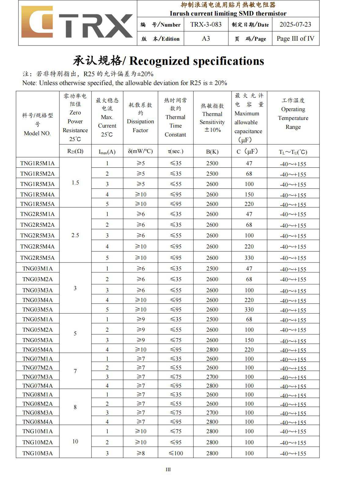
| Model | Zero-power resistance R25 (Ω) | Maximum steady-state current at 25°C, Imax (A) | Approximate thermal dissipation factor δ (mW/°C) | Approximate thermal time constant τ (s) | B value (K), ±10% | Maximum allowable capacitance C (μF) | Operating temperature TL–TU (°C) |
|---|---|---|---|---|---|---|---|
| TNG1R5M1A | 1.5 | 1 | ≥5 | ≤35 | 2500 | 47 | -40~+155 |
| TNG1R5M2A | 1.5 | 2 | ≥5 | ≤35 | 2500 | 68 | -40~+155 |
| TNG1R5M3A | 1.5 | 3 | ≥5 | ≤55 | 2600 | 100 | -40~+155 |
| TNG1R5M4A | 1.5 | 4 | ≥10 | ≤95 | 2600 | 150 | -40~+155 |
| TNG1R5M5A | 1.5 | 5 | ≥10 | ≤95 | 2600 | 220 | -40~+155 |
| TNG2R5M1A | 2.5 | 1 | ≥6 | ≤35 | 2600 | 47 | -40~+155 |
| TNG2R5M2A | 2.5 | 2 | ≥6 | ≤35 | 2600 | 68 | -40~+155 |
| TNG2R5M3A | 2.5 | 3 | ≥6 | ≤55 | 2600 | 100 | -40~+155 |
| TNG2R5M4A | 2.5 | 4 | ≥10 | ≤95 | 2600 | 220 | -40~+155 |
| TNG2R5M5A | 2.5 | 5 | ≥10 | ≤95 | 2600 | 330 | -40~+155 |
| TNG03M1A | 3 | 1 | ≥6 | ≤35 | 2500 | 47 | -40~+155 |
| TNG03M2A | 3 | 2 | ≥6 | ≤35 | 2600 | 68 | -40~+155 |
| TNG03M3A | 3 | 3 | ≥6 | ≤55 | 2600 | 100 | -40~+155 |
| TNG03M4A | 3 | 4 | ≥10 | ≤95 | 2600 | 220 | -40~+155 |
| TNG03M5A | 3 | 5 | ≥10 | ≤95 | 2600 | 330 | -40~+155 |
| TNG05M1A | 5 | 1 | ≥9 | ≤35 | 2500 | 68 | -40~+155 |
| TNG05M2A | 5 | 2 | ≥9 | ≤55 | 2600 | 100 | -40~+155 |
| TNG05M3A | 5 | 3 | ≥9 | ≤75 | 2600 | 150 | -40~+155 |
| TNG05M4A | 5 | 4 | ≥10 | ≤95 | 2800 | 220 | -40~+155 |
| TNG07M1A | 7 | 1 | ≥7 | ≤35 | 2600 | 100 | -40~+155 |
| TNG07M2A | 7 | 2 | ≥7 | ≤55 | 2600 | 100 | -40~+155 |
| TNG07M3A | 7 | 3 | ≥7 | ≤75 | 2700 | 100 | -40~+155 |
| TNG07M4A | 7 | 4 | ≥7 | ≤95 | 2800 | 100 | -40~+155 |
| TNG08M1A | 8 | 1 | ≥7 | ≤35 | 2600 | 100 | -40~+155 |
| TNG08M2A | 8 | 2 | ≥7 | ≤55 | 2600 | 100 | -40~+155 |
| TNG08M3A | 8 | 3 | ≥7 | ≤75 | 2700 | 100 | -40~+155 |
| TNG08M4A | 8 | 4 | ≥7 | ≤95 | 2800 | 100 | -40~+155 |
| TNG10M1A | 10 | 1 | ≥10 | ≤75 | 2800 | 100 | -40~+155 |
| TNG10M2A | 10 | 2 | ≥10 | ≤95 | 2800 | 100 | -40~+155 |
| TNG10M3A | 10 | 3 | ≥8 | ≤100 | 2800 | 100 | -40~+155 |
Unless otherwise stated, R25 tolerance is ±20%. Source: TRX-3-083, A3, 2025-07-23, Page III of IV, a different page-count convention from the preceding image. The image does not specify voltage or test conditions for maximum allowable capacitance, so these values are not used for cross-device energy comparisons.
Related reading cited by the original report
Chinese source titles are retained below. NTC进入SMD时代,精勤贴片热敏获客户认可大批量出货 拆解报告:麦多多70W 2A2C六合一氮化镓快充插座 拆解报告:绿联65W 2C1A超薄氮化镓充电器 拆解报告:GOSIRY果子理45W双USB-C氮化镓充电器 拆解报告:果子理60W双USB-C氮化镓充电器 拆解报告:小米90W氮化镓小布丁充电器 松田推出扛雷击贴片NTC,助力快充开发更小、更薄 特锐祥发布全新贴片热敏电阻(SMD-NTC) 三家厂商推出多款贴片Y电容,满足高功率密度快充应用