
Keep AC and DC ratings separate
Each AC rating is paired with a DC rating, without waveform, frequency or lifetime correlation. Use the rating that matches the application; do not convert by a simple peak or RMS ratio.
| Rated voltage | 400 / 500 / 700 / 900 VAC · 1,000 / 1,200 / 1,600 / 2,000 VDC |
|---|---|
| Capacitance | 0.001–0.1 µF |
| Tolerance | ±5% / ±10% |
| Operating temperature | −40 °C to +105 °C |
| Lead spacing | 10 / 15 / 22.5 mm |
Boxed double-sided metallized polypropylene film capacitors for high-voltage, high-frequency pulse circuits. 400–900 VAC / 1,000–2,000 VDC, 1–100 nF.
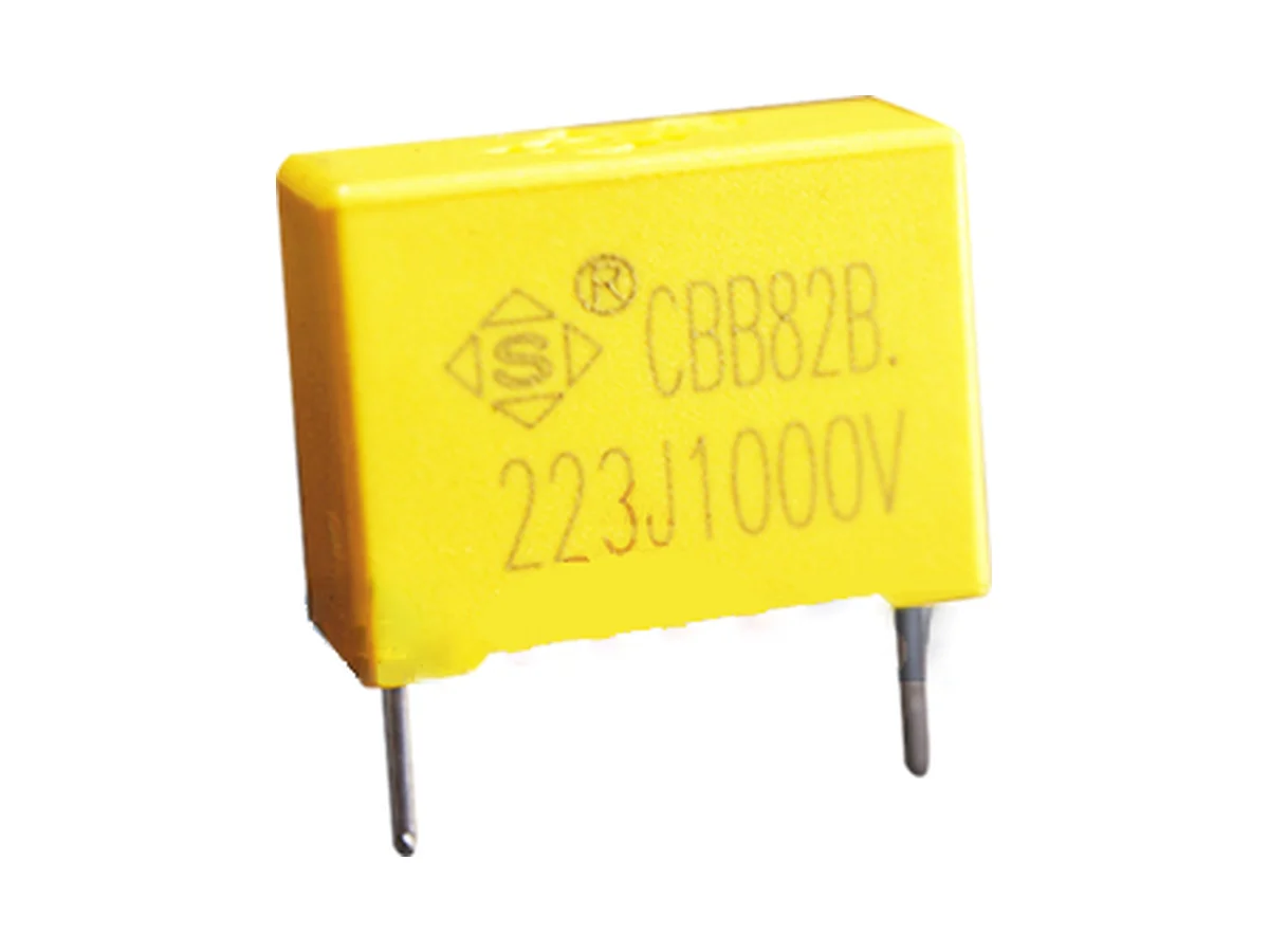
Double-sided metallized polypropylene film capacitors in a flame-retardant plastic box, for high-voltage, high-frequency pulse circuits and electronic ballasts. Rated 400 / 500 / 700 / 900 VAC, paired with 1,000 / 1,200 / 1,600 / 2,000 VDC. Capacitance 1–100 nF, J ±5% or K ±10%. Lead spacing 10, 15 and 22.5 mm. Operating temperature −40 °C to +105 °C.
Start with the AC or DC waveform and the resonant mission profile. Then check voltage basis, capacitance, dV/dt, peak and RMS current, frequency, hot-spot rise, fault response, lifetime and dimensions.
Specify DC bias, AC fundamental, peak voltage, rise and fall time, dV/dt, repetition rate, RMS current, harmonics, start-up or ignition, open-load and abnormal transients, together with ambient temperature, cooling and service hours.
The series covers 400/500/700/900 VAC, paired with 1,000/1,200/1,600/2,000 VDC, at 1–100 nF. Do not substitute one rating basis for the other; request the specification for any other rating.
Use Ipk = C·dV/dt and the measured spectrum to calculate peak, repetitive and RMS current, and check them against the dV/dt, K0, ESR, ESL, impedance, resonance, thermal-resistance and frequency-derating data (on request).
Check the electrode stack, internal series connection, self-healing behavior and fault response of the selected part number, together with its AC and pulse endurance, humidity and overload test data.
Match voltage, capacitance, tolerance, W/H/T, lead spacing, lead form, packing and soldering profile to the part number. Do not use reflow soldering; validate lead forming and vibration.
Download datasheets and technical documents for this series. Contact STE for approval documents covering your selected part. For editions not listed here, contact STE.
Documents for this series are available on request. Tell us the series, operating conditions and approvals you need.
Request documents| Product type | Boxed double-sided metallized polypropylene capacitor for high-voltage, high-frequency pulse duty |
|---|---|
| Construction | Polypropylene dielectric · double-sided metallized electrodes · plastic box |
| Self-healing | Not specified |
| Rated AC voltage | 400 · 500 · 700 · 900 VAC |
| Rated DC voltage | 1,000 · 1,200 · 1,600 · 2,000 VDC, paired with 400 · 500 · 700 · 900 VAC |
| Capacitance range | 1–100 nF · max. 27 nF at 500 and 700 VAC · 18 nF at 900 VAC |
| Capacitance tolerance | J ±5% · K ±10% |
| Operating temperature | −40 °C to +105 °C |
| Climatic category | 40/100/21 · derating between +100 °C and +105 °C on request |
| Storage temperature | +15 °C to +35 °C |
| Dissipation factor | tan δ ≤0.1% at 1 kHz, 1.0 Vrms, 20 °C |
| Insulation resistance | ≥50,000 MΩ at 100 VDC, 60 s, 20 °C |
| Voltage proof, terminal to terminal | 1.75 × UR for 5 s (UR basis: see datasheet) |
| Temperature coefficient of capacitance | Negative |
| Safety class | No X/Y class and no agency approval; do not use across the line or line to earth |
| Flame retardancy | Flame-retardant plastic box |
| Body dimensions | W, H, T and their dimensional tolerances are specified on the part drawing |
| Lead spacing | 10 · 15 · 22.5 mm, ±1.0 mm |
| Lead diameter | 0.6 ±0.05 mm at 10 mm spacing · 0.8 ±0.05 mm at 15 / 22.5 mm spacing |
| Lead forms and packing | Long straight · inner-bent · straight taped · bent taped |
| Taping | Tape dimensions specified for F = 10, 15 and 20–22.5 mm |
| Soldering profile, PP | Preheat ≤110 °C · soldering ≤120 °C · ≤15 s |
| Soldering profile, PE | Preheat ≤125 °C · soldering ≤160 °C · ≤15 s |
| Hand soldering | 350 °C max. · 3 s max. · ≥2 mm from the coating |
| Reflow soldering | Not permitted; film shrinkage can degrade performance |
| Environmental compliance | RoHS and REACH compliant; bromine-free and halogen-free. Material declarations on request. |
| Further data | On request: internal series connection and segmentation · self-healing and fault response · AC frequency, waveform and current limits · storage humidity and shelf life · frequency range, impedance, ESR, ESL and permissible voltage and current versus frequency · dV/dt, K0, peak, repetitive and RMS current, thermal resistance and hot-spot limit · capacitance-temperature curve · UL 94 class · pulse-life, AC endurance, damp-heat, overload, thermal-cycle, vibration and lead-strength test results |
Ranges by dielectric, package and lead style within this series.
| Variant | Body dimensions | Rated voltage / capacitance | Construction / tolerance | Lead / land pattern | Notes |
|---|---|---|---|---|---|
| N · 10 mm | Body dimensions specified on the part drawing | 400 VAC / 1,000 VDC · 1–5.6 nF | Double-sided metallized PP · J/K | P 10 ±1.0 · d 0.6 ±0.05 mm | Smallest body; 400 VAC / 1,000 VDC only. |
| Q · 15 mm | Body dimensions specified on the part drawing | 400 VAC: 6.8–27 nF · 500 VAC: 1–15 nF · 700 VAC: 1–6.8 nF | Double-sided metallized PP · J/K | P 15 ±1.0 · d 0.8 ±0.05 mm | Check waveform, dV/dt, RMS current and hot-spot limit per part number. |
| T · 22.5 mm | Body dimensions specified on the part drawing | 400 VAC: 33–100 nF · 500/700 VAC to 27 nF · 900 VAC: 1–18 nF | Double-sided metallized PP · J/K | P 22.5 ±1.0 · d 0.8 ±0.05 mm | Highest voltage and capacitance values; check AC and pulse endurance, vibration, board support and fault response per part number. |
Each AC rating is paired with a DC rating, without waveform, frequency or lifetime correlation. Use the rating that matches the application; do not convert by a simple peak or RMS ratio.
Double-sided metallization can be built with different carrier films, internal series structures and margins. Before relying on self-healing, fail-open behavior or overload capability, request the construction and fault-response data of the selected part.
Measure the actual voltage and current spectrum, including ignition and abnormal modes. Combine I = C·dV/dt with RMS current, ESR and thermal resistance to verify hot-spot rise and resonance margin.
Record switching frequency, ignition pulse, lamp-open and end-of-life behavior, enclosure temperature and target service hours. Validate the selected part number over the complete operating sequence.
For other voltage ratings, values above 100 nF or below 1 nF, or 7.5 and 27.5 mm lead spacing, request the part specification, drawing and qualification report. Do not extrapolate.
Apply the PP/PE soldering limits to the actual construction and do not use reflow soldering. Keep lead-forming stress away from the epoxy seal, and validate cleaning, coating, vibration and thermal cycling, especially for the 26 mm body.
Example ordering code. Not every combination is available.
HB · G2 · 153 · J · Q · 1 · B0 · 180 · 120 · 060 · E · S · 0
| Code | Meaning |
|---|---|
| HB | Series code: MMKP82/CBB82B |
| G2 | Rated voltage code: G2 = 400 VAC; H2 = 500 VAC, V1 = 700 VAC, X1 = 900 VAC; DC voltage codes on request |
| 153 | Capacitance code: 153 = 15 nF |
| J | Capacitance tolerance: J = ±5%, K = ±10% |
| Q | Lead spacing: Q = 15 mm; N = 10 mm, T = 22.5 mm |
| 1 | Lead form: 1 = long straight, 2 = inner-bent, 5 = straight taped, 6 = bent taped |
| B0 | Lead length code: B0 = 20.0 mm |
| 180 | Body width: 180 = 18.0 mm |
| 120 | Body height: 120 = 12.0 mm |
| 060 | Body thickness: 060 = 6.0 mm |
| E | Environmental code: E = RoHS, F = RoHS and halogen-free |
Check electrical ratings, dimensions and ordering options in the datasheet. Send us your requirements to confirm the final part number and availability.
Showing 25 of 287 listed part numbers
| Datasheet | |
|---|---|
| HB2E224JT135260200110EST | On request |
| HB2E394JT135265170085EST | On request |
| HB2E473JQ1B0180120060EST | On request |
| HB2E474JT135265190100EST | On request |
| HB2E682JN1B0130090040EST | On request |
| HB2H153KQ1B0180120060EST | On request |
| HB2J103JN1B0130110050EST | On request |
| HB2J104JQ132180135075FET | On request |
| HB2J104JQ132180160100EST | On request |
| HB2J104JQ135180135075EST | On request |
| HB2J104JQ135180160100EST | On request |
| HB2J104JQ135180160100FET | On request |
| HB2J104JQ135180190110EST | On request |
| HB2J104JQ1A2180160100EST | On request |
| HB2J104JQ1A5180135075EST | On request |
| HB2J104JQ1A5180160100EST | On request |
| HB2J104JQ1A8180135075EST | On request |
| HB2J104JQ1B0180135075EST | On request |
| HB2J104JQ1B0180160100FET | On request |
| HB2J104JQ1B0180190110ES0 | On request |
| HB2J104JQ1B0180190110EST | On request |
| HB2J104JQ280180190110EST | On request |
| HB2J104JT135265165070EST | On request |
| HB2J105JV1A5310250140EVT | On request |
| HB2J123JN1B0130110050EST | On request |
Need a value that is not listed? Send us your specification.