
R25 tolerance is not temperature accuracy
Temperature error combines R25 and B (R/T) tolerance, ADC, reference and divider-resistor error, self-heating, thermal gradients and drift. Build the error budget at every critical temperature.
| R25 | 1 kΩ–1.3 MΩ |
|---|---|
| B25/50 | 3,380–4,500 K |
| Case size | 0201 / 0402 / 0603 / 0805 |
| R25 tolerance | ±1% / ±2% / ±3% / ±5% |
Glass-coated SMD NTC thermistors for PCB temperature sensing and compensation. Case sizes 0201 to 0805, R25 1 kΩ–1.3 MΩ.
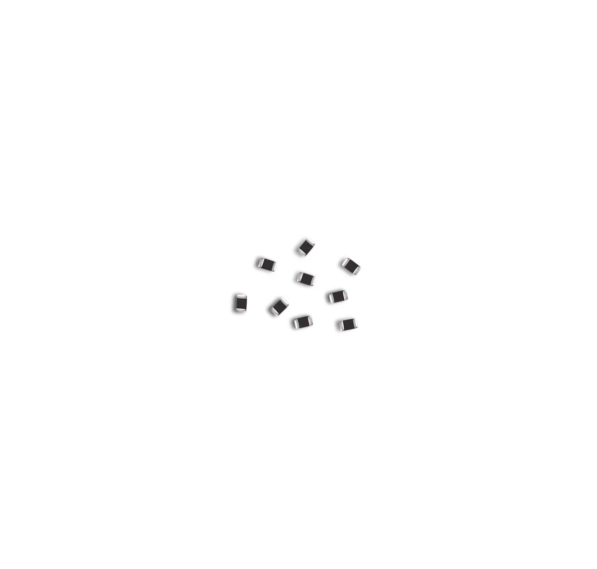
Part numbers and datasheets on request. Tell us the application, your specifications and the expected volume, and an STE engineer will reply by email.
Part number:
Datasheets, technical documents and approval certificates for this series. English editions of documents marked “Chinese” are available on request.
Glass-coated chip NTC thermistors in 0201, 0402, 0603 and 0805 sizes for PCB temperature sensing and compensation. R25 1 kΩ–1.3 MΩ, B25/50 3,380–4,500 K, R25 tolerance ±1% to ±5%. Operating temperature −55 °C to +125 °C.
| Function | SMD NTC thermistor for temperature measurement and compensation. Resistance falls as temperature rises. |
|---|---|
| Construction | Sintered NTC ceramic with glass surface coating and wraparound external electrodes |
| Case sizes, inch [metric] | 0201 [0603] · 0402 [1005] · 0603 [1608] · 0805 [2012] |
| Operating temperature | −55 °C to +125 °C |
| R25 range | 1 kΩ–1.3 MΩ; available values depend on case size and B value |
| R25 tolerance codes | F ±1% · G ±2% · H ±3% · J ±5% |
| B-value reference codes | A = B25/85 · B = B25/50 |
| B-value tolerance | F = ±1%; B value and reference temperatures per part number |
| B25/50 range | 3,380–4,500 K |
| B25/85 range | 3,435–4,582 K |
| Temperature accuracy | R25 and B tolerances do not state a ±°C accuracy. Calculate temperature error from the R/T table. |
| Permissible sensing current, 0201 | 0.06–1.00 mA at 25 °C (1–220 kΩ) |
| Permissible sensing current, 0402 | 0.03–1.00 mA at 25 °C (1–680 kΩ) |
| Permissible sensing current, 0603 | 0.02–1.00 mA at 25 °C (1 kΩ–1.3 MΩ) |
| Permissible sensing current, 0805 | 0.02–1.40 mA at 25 °C (1 kΩ–1.3 MΩ) |
| Rated power | 100 mW at 25 °C |
| Dissipation constant | 1.0 mW/°C |
| Thermal time constant | <3 s (0201, 0402) · <5 s (0603, 0805) |
| Dimensions, 0201 | L 0.60 ±0.05 · W 0.30 ±0.05 · T 0.30 ±0.05 · terminal a 0.15 ±0.05 mm |
| Recommended land pattern, 0201 | A 0.20–0.30 · B 0.25–0.35 · C 0.25–0.35 mm |
| Dimensions, 0402 | L 1.00 ±0.15 · W 0.50 ±0.15 · T 0.50 ±0.15 · terminal a 0.25 ±0.10 mm |
| Recommended land pattern, 0402 | A 0.45–0.55 · B 0.40–0.50 · C 0.45–0.55 mm |
| Dimensions, 0603 | L 1.60 ±0.15 · W 0.80 ±0.15 · T 0.80 ±0.15 · terminal a 0.30 ±0.20 mm |
| Recommended land pattern, 0603 | A 0.60–0.80 · B 0.60–0.70 · C 0.60–0.80 mm |
| Dimensions, 0805 | L 2.00 ±0.20 · W 1.25 ±0.20 · T 0.85 ±0.20 · terminal a 0.50 ±0.30 mm |
| Recommended land pattern, 0805 | A 1.00–1.10 · B 0.60–0.70 mm · C on request |
| Environmental compliance | RoHS and REACH compliant; material declarations and halogen status on request |
| Tape and reel | 0201: 15,000/reel · 0402: 10,000/reel · 0603: 4,000/reel · 0805: 4,000/reel · paper carrier tape |
| Carrier tape thickness | 0201/0402: 0.50 ±0.15 · 0603: 0.80 ±0.15 · 0805: 0.85 ±0.20 mm; full tape and reel drawings in the datasheet |
| Storage | −10 °C to +40 °C · ≤75% RH · six months; avoid dust, corrosive, reducing or flammable gases, sunlight, water, oils, chemicals, solvents, pressure extremes and strong vibration |
| Reflow profile | Ramp 1–2 °C/s · preheat 150–190 °C for 90 ±30 s · above 240 °C for 20–40 s · peak 260 °C, 10 s max. · two cycles max. · SAC305 |
| Hand soldering | Iron 30 W max., 360 °C max., 3 s max. · preheat 150 °C/60 s · one cycle · SAC305 |
| Wave soldering | Not specified for this series |
| Further data on request | Resistance–temperature (R/T) table · maximum voltage and power derating versus ambient temperature · MSL rating and floor life · solderability, humidity, endurance and thermal-cycle test results |
| Automotive use | No AEC-Q200 qualification is specified for this series |
Ranges by dielectric, package and lead style within this series.
| Variant | Body dimensions | R25 / B25/50 range | Sensing current / thermal data | Lead / land pattern | Notes |
|---|---|---|---|---|---|
| 0201 [0603 metric] | L 0.60 × W 0.30 × T 0.30 mm nom. | 1–220 kΩ · B25/50 3,380–4,485 K | 0.06–1.00 mA · 100 mW · 1.0 mW/°C · <3 s | A 0.20–0.30 · B/C 0.25–0.35 mm | Smallest size, for densely packed portable electronics. Verify placement, self-heating and handling. |
| 0402 [1005 metric] | L 1.00 × W 0.50 × T 0.50 mm nom. | 1–680 kΩ · B25/50 3,380–4,500 K | 0.03–1.00 mA · 100 mW · 1.0 mW/°C · <3 s | A/C 0.45–0.55 · B 0.40–0.50 mm | Compact size with R25 from 1 to 680 kΩ. Design with the R/T table of the part number. |
| 0603 [1608 metric] | L 1.60 × W 0.80 × T 0.80 mm nom. | 1 kΩ–1.3 MΩ · B25/50 3,380–4,500 K | 0.02–1.00 mA · 100 mW · 1.0 mW/°C · <5 s | A/C 0.60–0.80 · B 0.60–0.70 mm | Widest R25 range, with a larger handling margin. |
| 0805 [2012 metric] | L 2.00 × W 1.25 × T 0.85 mm nom. | 1 kΩ–1.3 MΩ · B25/50 3,380–4,500 K | 0.02–1.40 mA · 100 mW · 1.0 mW/°C · <5 s | A 1.00–1.10 · B 0.60–0.70 mm · C on request | Largest size, with the highest permissible sensing current. |
Define the temperature range and the allowed system error first. Then select the R25/B curve, case size and measurement current. Verify thermal placement, self-heating, divider and ADC tolerance, and assembly stress before production release.
Set the minimum and maximum sensor temperature, required ±°C accuracy, response time, drift, calibration method and the safety consequence of a sensing error. R25 tolerance alone does not define accuracy across the range.
Choose R25 for the divider and ADC range, and B25/50 or B25/85. Use an R/T table in 1 °C steps or finer, with its tolerance band, across the application range.
Calculate divider current and power at every temperature and supply tolerance. Keep self-heating within the error budget. Stay within the permissible sensing current; maximum voltage and power derating on request.
Place the NTC close to the monitored object. Account for copper area, airflow, nearby heat-generating parts and board temperature gradients. Use the recommended land pattern and verify response on the assembled product.
Check terminal finish, tape and reel, MSL and floor life, reflow profile, board-flex limits and environmental declarations for the selected part number, and qualify it in the target application.
Temperature error combines R25 and B (R/T) tolerance, ADC, reference and divider-resistor error, self-heating, thermal gradients and drift. Build the error budget at every critical temperature.
A single B value approximates the curve only between its two reference temperatures. Base interpolation and firmware thresholds on the R/T table or approved coefficients. Do not mix B25/50 and B25/85 values.
Divider current heats the NTC and shifts the reading. Use pulsed excitation where appropriate. Verify the assembled thermal path at maximum supply voltage and at the highest and lowest resistance.
Copper area, vias, nearby power parts, airflow and enclosure contact can make board temperature differ from the monitored object. Correlate the placement against reference thermometry in the finished product.
Use the recommended land pattern, balanced solder volume, controlled placement force and board support. After reflow, avoid board bending, depaneling and connector loads; they can crack the chip.
The 0201–0805 series is for temperature sensing and compensation. Surge, inrush current, flammability and automotive ratings of SMD power NTC parts do not apply to this series.