CY-AAEC-Q200

Automotive CY Series Safety Certified Ceramic Capacitors (Class X1/Y1, AEC-Q200)

Safety classX1 760 VAC / Y1 500 VAC (IEC 60384-14)
Automotive qualificationAEC-Q200 qualified part numbers available
CapacitanceY5P 100–2,200 pF · Y5U 330–4,700 pF
Temperature cycling1,000 cycles, −55 °C to +125 °C
Lead spacing10.0 mm
ApprovalsCQC · VDE/ENEC · UL/cUL
CQC certification markVDE certification markENEC certification markUL certification mark

Automotive radial ceramic safety capacitors, Class X1 760 VAC / Y1 500 VAC, 100–4,700 pF. AEC-Q200 qualified part numbers available.

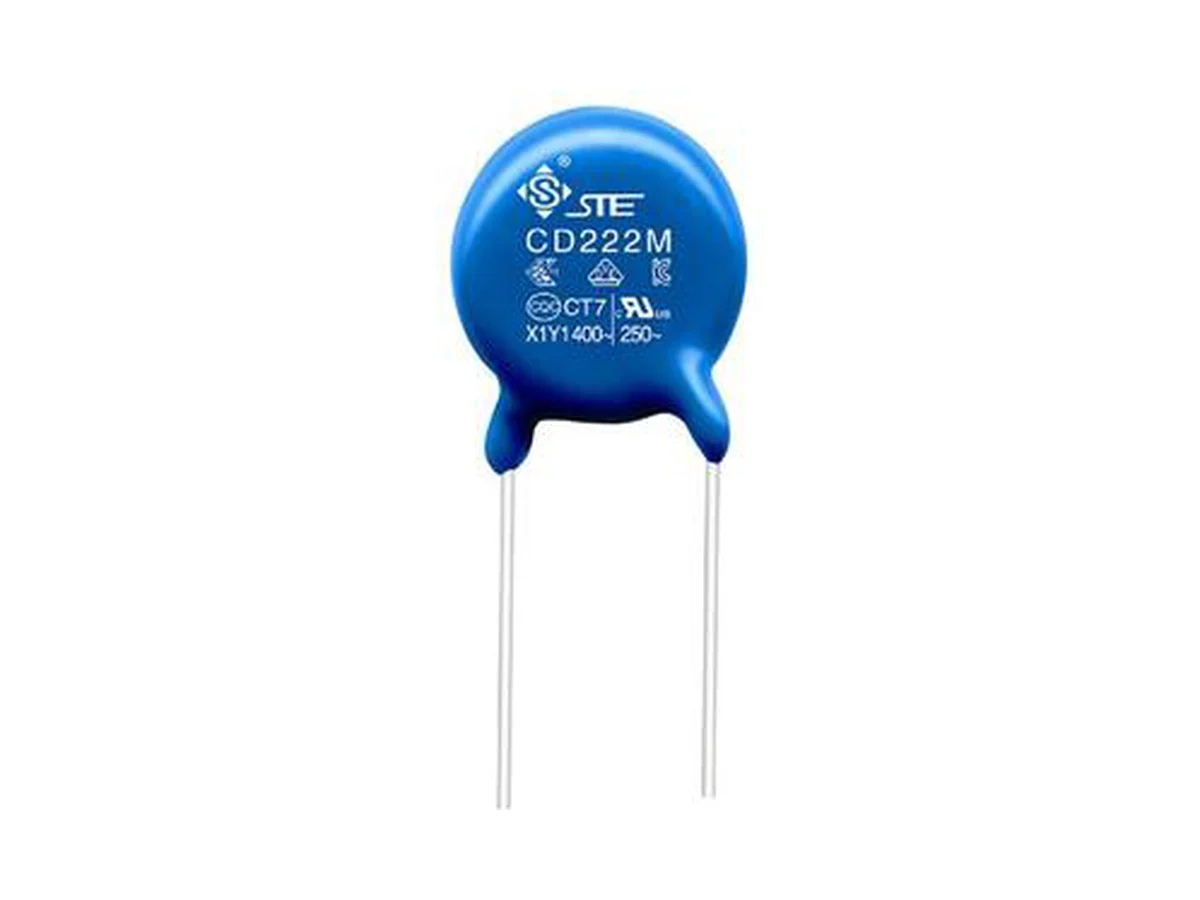
Series product photograph

Part numbers

41

Showing 25 of 41 part numbers

Q07B1D101KN0B2CQN0
Q07B1D221KN0B2CQN0
Q07B2D101KA1B2CQNW
Q07B2D101KP0T2CQPW
Q07B2D221KA1B2CQN0
Q07B8D101KP0T2FQN0
Q07B8D221KP0T2CQP0
Q08B1D331KN0B2CQN0
Q08E1D102MN0B2CQN0
Q08E2D102MA1B2CQA0
Q08E2D102MN0B2CQN0
Q08E2D102MP0P2CQAW
Q08E3D102MA0B2CQN0
Q08E3D102MA5B2CQN0
Q09B1D471KN0B2CQN0
Q09B2D471KP0T2CQP0
Q09B3D471KA4B2CQN0
Q09B8D471KP0T2CQP0
Q10B1D681KN0B2CQN0
Q10E1D152MN0B2CQN0
Q11E1D222MN0B2CQN0
Q11E2D222MN0B2CQN0
Q11E3D222MA5B0SQN0
Q12B1D102KN0B2CQN0
Q12B2D102KB0B2CQN0

Need a value that is not listed? Send us your specification.

Engineering details

Overview

Radial disc ceramic safety capacitors for automotive power electronics, Class X1 760 VAC / Y1 500 VAC to IEC 60384-14, for EMI suppression and coupling across reinforced insulation. Y5P 100–2,200 pF and Y5U 330–4,700 pF. AEC-Q200 qualified part numbers available; 85 °C / 85% RH for 1,000 h; 1,000 temperature cycles from −55 °C to +125 °C.

Series features

  • Class X1 760 VAC / Y1 500 VAC to IEC 60384-14 for automotive power-conversion interfaces
  • Dielectrics Y5P 100–2,200 pF and Y5U 330–4,700 pF
  • AEC-Q200 qualified part numbers available; 85 °C / 85% RH for 1,000 h; 1,000 temperature cycles from −55 °C to +125 °C
  • Safety approvals: CQC, VDE/ENEC, UL/cUL
Specifications
FunctionRadial single-layer ceramic safety capacitor for X1/Y1 EMI suppression and isolation coupling. The capacitor alone is not a complete reinforced-insulation system or equipment approval.
Safety classIEC 60384-14 · X1 760 VAC / Y1 500 VAC
Reinforced insulationY1 supports reinforced-insulation positions only when creepage, clearance, pollution degree, overvoltage and abnormal-condition design of the equipment also comply
Automotive qualificationAEC-Q200 qualified part numbers available; AEC-Q200 revision, qualification report and qualified part-number list on request
Damp heat85 °C / 85% RH, 1,000 h
Annex I humidity gradeNot assigned in VDE approval 40056133; the 85/85 test is not an Annex I grade IIIB rating
Temperature cycling1,000 cycles, −55 °C to +125 °C
Climatic category40/125/21 (CQC, VDE)
Operating temperature−40 °C to +125 °C (approval range); operating grade and voltage derating on request
Capacitance rangeY5P 100–2,200 pF (12 values) · Y5U 330–4,700 pF (12 values)
Capacitance toleranceY5P K ±10% · Y5U K ±10% up to 820 pF, M ±20% from 1,000–4,700 pF
Body dimensions, Y5PD max. 7.5–18.0 · T max. 5.0–6.5 mm, depending on value
Body dimensions, Y5UD max. 7.5–17.0 · T max. 6.0–6.5 mm, depending on value
LeadsF 10.0 ±0.5 mm · d 0.60 or 0.65 ±0.05 mm, depending on part
Measuring conditionsCapacitance and dissipation factor at 25 °C · 1 kHz · 1 Vrms
Dissipation factor≤2.5% (initial)
Insulation resistance≥10,000 MΩ
Dielectric strength4,000 VAC
DC ratingRated for X1/Y1 AC. VDE Annex H covers 1,500 VDC for Y5U/Y5V only; DC rating of individual part numbers on request
Leakage currentNo component limit specified; calculate from maximum C, f and V and check the touch-current budget of the equipment
Lead forms and coating extensionLong straight · short straight · single outer-bent · front/rear raised; coating extension ≤2.5 mm (body ≤10 mm) or ≤3.0 mm (body >10 mm) where applicable
Bulk lead lengthLong straight ≥16.0 mm · short/bent 2.5–<6.0 mm ±0.5 or 6.0–10.0 mm ±1.0
TapingF 10 mm; P0 12.7 / P 25.4 mm or P0 15 / P 15 mm; 18 mm carrier tape; seating height depends on lead form
Wave solderingPreheat 30–130 s to 115 °C · rapid rise to 260 °C max. · solder ≤10 s · cooling ≤5 °C/s; validate immersion depth and board thermal mass
Hand rework360 °C max. · 3 s max. · solder joint ≥2 mm from coating
Further data on requestDamp-heat bias voltage, sample size, recovery and post-test limits · temperature-cycling dwell, transfer time and post-test limits · insulation-resistance measuring voltage and charging time · dielectric-strength frequency, duration and ramp · Y1 impulse voltage, 1.2/50 µs waveform, polarity and number of pulses · capacitance versus temperature, AC/DC bias, frequency and aging for Y5P, Y5U and Y5V · reflow suitability, cleaning and coating compatibility, lead-forming limits, storage conditions and shelf life · endurance, biased humidity, vibration, mechanical shock, lead strength and solder-heat test results
Selection guide

Start from the insulation diagram of the equipment and the maximum continuous AC/DC voltage. Then check Y-capacitor leakage, effective capacitance, impulse duty, AEC-Q200 and approval scope, humidity and cycling data, dimensions, marking and assembly process for one part number.

  1. Classify the insulation and circuit position

    Identify line-to-earth, primary-to-secondary or across-the-line duty from the equipment standard. Confirm reinforced or basic insulation, pollution degree, creepage, clearance and abnormal conditions before selecting Y1 or X1.

  2. Define continuous AC, DC and impulse voltage

    Use the approval voltage code of the selected part. 1,500 VDC applies only to Y5U/Y5V under VDE Annex H. Y1 impulse waveform, polarity, count and acceptance on request. The 4 kVAC proof test is not an impulse or working rating.

  3. Set capacitance from EMI and leakage together

    Calculate common-mode attenuation and I = 2πfCV at maximum voltage, frequency and tolerance for every Y capacitor. Use temperature, bias, frequency and aging curves so that nominal capacitance is not mistaken for effective capacitance.

  4. Request automotive and safety documentation

    Request the AEC-Q200 revision and report, qualified part numbers, grade, site, stress groups, sample sizes, results and PPAP/change control, together with the current CQC, VDE and UL scope for the same marking and construction.

  5. Confirm body, leads, packing and process

    Check the drawing, blue coating and marking, lead form and length, taping, soldering, cleaning, storage and post-process acceptance of the selected part number. Availability of Y5V and values above 4,700 pF on request.

Approvals & reliability

Approvals & qualifications

AEC-Q200 stress qualification and IEC 60384-14 safety approvals are separate. The approvals below cover the CY construction. Approval and AEC-Q200 coverage of individual part numbers on request.

AgencyStandardCertificateScope
CQC certification markCQCIEC 60384-14:2013 + AMD1:2016CQC23001374885CY X1/Y1, 100–10,000 pF; X1 760/500/440/400 VAC, Y1 500/400/250 VAC; Y5P/Y5U/Y5V, tolerance K/M, 40/125/21, class B; Annex H for Y5U/Y5V. Issued 28 Jan 2023, valid subject to surveillance.
VDE certification markENEC certification markVDE / ENECDIN EN / EN 60384-1440056133CY X1/Y1, 100–10,000 pF, AC ratings as above; Annex H 1,500 VDC for Y5U/Y5V only. No Annex I humidity grade assigned.
UL certification markUL / cULUL / Canadian 60384-14 component recognitionE208107Recognized component, USA and Canada: Y5P 100–2,200 pF, Y5U/Y5V 330–10,000 pF, X1/Y1 AC ratings, 1,500 VDC for higher-K constructions, −40 °C to +125 °C.

Each certificate covers the types and ratings listed on it.

Design notes

Y1 is part of a complete insulation system

Select from the insulation diagram of the equipment, not from the capacitor marking alone. PCB creepage and clearance, pollution degree, accessible conductors, enclosure, protective earth and abnormal tests remain system responsibilities.

Calculate leakage at maximum conditions

Use maximum capacitance, tolerance, line frequency and voltage for each Y capacitor and total the complete network. Keep margin for the temperature, bias and aging behavior of the dielectric and for the touch-current limits of the equipment.

Keep proof, impulse and working voltage apart

X1/Y1 AC ratings, the 1,500 VDC Annex H scope, the 4 kVAC proof test and a Y1 impulse test are different quantities. Check each value and its test method for the selected part and circuit position.

Safety approval and AEC-Q200 are separate

CQC, VDE and UL approvals confirm the safety classification of the component. They do not establish automotive stress qualification, PPAP, site traceability or mission-profile life. Both must apply to the same part number.

Y5V and values above 4,700 pF

The automotive range covers Y5P and Y5U up to 4,700 pF. For Y5V, 10 nF or other code options, availability and electrical, dimensional, marking, packing and qualification data on request.

Control the radial assembly process

Observe the wave-soldering profile and the 360 °C hand-rework limit. Keep heat and bending stress away from the coating. Review cleaning, coating, storage, shelf-life and vibration data before production.

Part numbering

Example ordering code. Not every combination is available.

Q · 09 · B · 1 · D · 471 · K · N0 · B · 2 · C · Q · N · 0

CodeMeaning
QRated-voltage code: Q = Y1
09Body diameter code: 09 = 9 mm
BTemperature characteristic: B = Y5P, E = Y5U, F = Y5V
1Lead form: 1 = long straight, 2 = single outer-bent, 3 = short straight, 8 = front/rear raised
DLead spacing: D = 10.0 mm
471Capacitance code: 471 = 470 pF
KCapacitance tolerance: K ±10%, M ±20%
N0Lead length or taped seating-height code, depending on lead form and packing
BPackaging: B = bulk, T = tape
2Environmental code: 2 = RoHS + halogen-free, 0 = RoHS
CMarking and approval voltage code: C = X1 760 VAC / Y1 500 VAC
QAutomotive product code
NInternal management code
0Internal management code