
X1 and X2 are not interchangeable
Both are across-the-line classes, but X1 is selected for the higher impulse category of the equipment environment. Confirm the system standard, overvoltage category and surge source before choosing the class.
| Safety class | X1, across-the-line |
|---|---|
| THB test | 85 °C / 85% RH · 240 VAC · 500 h |
| Rated voltage | 330 / 440 / 480 / 500 / 530 VAC |
| Capacitance | 0.001–1.0 µF |
| Impulse test voltage | 4 kV (CR ≤1.0 µF) |
| Operating temperature | −40 °C to +110 °C |





Boxed metallized polypropylene film capacitors for across-the-line EMI suppression in humid environments, Class X1. Rated 330–530 VAC, 1 nF–1 µF.
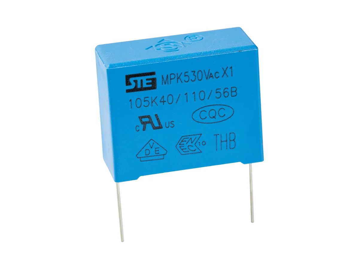
Showing 4 of 4 part numbers
| X1S1473KQ1B0180135075EV8 | 0.047 | ±10 | 440 | X1 |
|---|---|---|---|---|
| X1S1473KQ1B0180145085EV8 | 0.047 | ±10 | 440 | X1 |
| X1S1684KT1B0260250150PX8 | 0.68 | ±10 | 440 | X1 |
| X1S3684KT1B0260250150PX8 | 0.68 | ±10 | 480 | X1 |
— = not specified
Need a value that is not listed? Send us your specification.
Datasheets, technical documents and approval certificates for this series. English editions of documents marked “Chinese” are available on request.
Boxed metallized polypropylene film capacitors for across-the-line (L–N) EMI suppression under higher impulse stress and in humid environments, Class X1 to IEC / EN / UL 60384-14. Rated 330, 440, 480, 500 and 530 VAC; 1 nF–1 µF; tolerance ±10% or ±20%. Impulse test 4 kV, 24 pulses (CR ≤1.0 µF). Biased humidity test: 85 °C / 85% RH, 240 VAC, 500 h. Operating temperature −40 °C to +110 °C.
| Safety function | Class X1 · across-the-line (L–N) suppression, higher impulse class · not for line-to-earth (Y) positions |
|---|---|
| Construction | Metallized polypropylene film · boxed, resin-encapsulated |
| Reference standards | IEC / EN / UL 60384-14 · GB/T 6346.14-2023 |
| Rated AC voltage UR | 330 · 440 · 480 · 500 · 530 VAC |
| Capacitance range | 0.001–1.0 µF · available values depend on rated voltage, body size and approval scope |
| Capacitance tolerance | ±10% (K) · ±20% (M) |
| Operating temperature | −40 °C to +110 °C |
| Climatic category / flammability | 40/110/56 · passive flammability category B |
| Dissipation factor | tan δ ≤0.1% |
| Insulation resistance, CR ≤0.33 µF | ≥15,000 MΩ at 20 °C, 100 VDC, 60 s |
| Insulation resistance, CR >0.33 µF | Time constant ≥5,000 s (T = IR [MΩ] × CN [µF]) at 20 °C, 100 VDC, 60 s |
| Voltage proof, terminal to terminal | 4.3 × UR DC, 5 s |
| Voltage proof, terminals to case | 2 × UR + 1,500 VAC, min. 2,000 VAC |
| Impulse test voltage | 4 kVDC for CR ≤1.0 µF; a test condition, not a continuous or repetitive rating |
| Impulse sequence | 24 pulses · 9 s charge / 2 s discharge cycle |
| Self-ignition test | U~ = UR · Ui = 4.0 kV · 20 discharges of the energy-storage capacitor per sample · 5 s interval |
| Biased humidity test (THB) | 85 ±2 °C · 85 ±2% RH · 240 VAC · 500 h |
| THB acceptance | |ΔC/C| ≤10%; other post-test limits on request |
| IEC 60384-14 Annex I grade | None: VDE certificate 40054631 includes no Annex I humidity-robustness grade. The 500 h THB test is an STE test, not a certified grade. |
| DC operation | No continuous DC rating; the VDE approval includes no Annex H (DC) approval |
| Body dimensions | W 10–41.5 · H 9–35 · T 4–22.5 mm, depending on rated voltage and capacitance |
| Lead pitch | 7.5 · 10 · 15 · 22.5 · 27.5 · 37.5 mm |
| Lead diameter | 0.6 mm (pitch 7.5–10 mm) · 0.8 mm (15–27.5 mm) · 1.0 mm (37.5 mm) |
| Lead and packing forms | Long straight · inner-bent · straight, taped · bent, taped |
| Hand soldering / rework | Iron ≤350 °C · ≤3 s · ≥2 mm from the coating |
| Reflow soldering | Not permitted; film shrinkage can degrade performance |
| Storage | In unopened package: ≤35 °C, ≤70% RH, ≤12 months. Keep away from corrosive gases to preserve lead solderability. |
| Further data | On request: voltage-proof duration, terminals to case; dV/dt, peak-current waveform, RMS current, ESR/impedance, temperature rise and repetitive-pulse derating; dry-heat life, thermal cycling, vibration and lead strength, with post-test limits |
Ranges by dielectric, package and lead style within this series.
| Variant | Body dimensions | Rated voltage / capacitance | Construction / class | Lead / land pattern | Notes |
|---|---|---|---|---|---|
| J · 7.5 mm | W 10 · H 9–15 · T 4–8 mm | 330–530 VAC · 0.001–0.0056 µF | Metallized PP · X1 · K/M | P 7.5 ±0.5 · d 0.6 ±0.05 mm | Smallest pitch, low capacitance values; 500 and 530 VAC parts use larger cases. |
| N · 10 mm | W 13 · H 11–15 · T 5–8 mm | 330–530 VAC · 0.001–0.01 µF | Metallized PP · X1 · K/M | P 10 ±0.5 · d 0.6 ±0.05 mm | Compact, low capacitance values; body height and thickness depend on rated voltage. |
| Q · 15 mm | W 18 · H 11–19 · T 5–11 mm | 330–530 VAC · 0.01–0.068 µF | Metallized PP · X1 · K/M | P 15 ±0.5 · d 0.8 ±0.05 mm | The part-number suffix defines body size and lead length. |
| T · 22.5 mm | W 26.5 · H 15–23 · T 6–13 mm | 330–530 VAC · 0.047–0.18 µF | Metallized PP · X1 · K/M | P 22.5 ±0.5 · d 0.8 ±0.05 mm | — |
| V · 27.5 mm | W 31–31.5 · H 20–28 · T 11–18 mm | 330–530 VAC · 0.1–0.33 µF | Metallized PP · X1 · K/M | P 27.5 ±0.5 · d 0.8 ±0.05 mm | Mid-to-high capacitance values. Availability on request. |
| L · 37.5 mm | W 41.5 · H 28–35 · T 14–22.5 mm | 330–530 VAC · 0.39–1.0 µF | Metallized PP · X1 · K/M | P 37.5 ±0.5 · d 1.0 ±0.05 mm | Largest case. Capacitance values: see part drawing. Pulse, current and thermal limits on request. |
Choose X1 because the circuit and the equipment standard require its impulse class, not because the nominal AC voltage is high. Then select rated voltage, capacitance, pulse duty, humidity profile and the case and lead construction together.
Use X1 between supply conductors where the applicable equipment standard and impulse environment require the higher class. It is not a line-to-earth Y capacitor and cannot establish a protective insulation path.
Choose 330–530 VAC for the approved construction. Compare the 4 kV / 24-pulse test sequence with the real surge waveform, repetition rate and source impedance. Proof and impulse tests are test conditions, not continuous ratings.
Use the K or M tolerance and the tan δ condition, then calculate RMS current and self-heating for the actual spectrum. ESR/impedance, dV/dt and current data for switching or high-line filters are available on request.
The THB test is 500 h at 85 °C / 85% RH and 240 VAC, with a capacitance-change limit only. The VDE approval grants no Annex I grade. The full report, post-test limits and mission-profile correlation are available on request.
Specify W/H/T, pitch, lead diameter and form and packing for each capacitance and voltage. For 37.5 mm parts, see the part drawing for capacitance values. Validate soldering, cleaning and coating; do not reflow-solder.
CQC, VDE/ENEC, IECEE CB and UL/cUL approvals cover MPK X1 from 1 nF to 1 µF at 330–530 VAC. The VDE approval includes neither an Annex H (DC) approval nor an Annex I humidity grade.
| Agency | Standard | Certificate | Scope |
|---|---|---|---|
| CQC | IEC 60384-14:2013 + AMD1:2016 / GB/T scope | CQC22001337767 | MPK X1, 0.001–1.0 µF, 330/440/480/500/530 VAC, ±10% (K) or ±20% (M), passive flammability category B, 40/110/56. Issued 7 Apr 2022. |
| VDE / ENEC | EN 60384-14:2017 | 40054631 | MPK X1, 0.001–1.0 µF, 330/440/480/500/530 VAC, K/M, climatic category 40/110/56, passive flammability category B. No Annex H (DC) approval; no Annex I humidity grade. |
| IECEE CB | IEC 60384-14:2013 + AMD1:2016 | DE1-65967 | MPK X1, 0.001–1.0 µF, K/M, 330/440/480/500/530 VAC, 40/110/56/B. Test report 288316-TL3-1. |
| UL / cUL | UL 60384-14 | E208107 | MPK X1, 0.001–1.0 µF, 330/440/480/500/530 VAC, −40 to +110 °C, ±10% (K) or ±20% (M). No humidity grade. |
Each certificate covers the types and ratings listed on it.
Initial characteristics, an impulse test (4 kV, 24 pulses), a self-ignition test and a biased damp-heat test (500 h) are specified.
| Test | Condition | Acceptance |
|---|---|---|
| Impulse test | 4 kVDC · 24 pulses · 9 s charge / 2 s discharge · CR ≤1.0 µF | Circuit, source impedance, waveform, peak current and post-test ΔC, tan δ, IR and voltage-proof limits on request |
| Self-ignition test | U~ = UR · Ui = 4.0 kV · 20 discharges per sample · 5 s interval | Energy-storage capacitance, source impedance and pass criteria on request |
| Biased damp heat (THB) | 85 ±2 °C · 85 ±2% RH · 240 VAC · 500 h | |ΔC/C| ≤10%; post-test tan δ, IR, voltage-proof, visual and sample-size criteria on request |
| Initial characteristics | tan δ ≤0.1%; IR ≥15,000 MΩ or time constant ≥5,000 s; voltage proof 4.3 × UR DC, terminal to terminal | Measurement conditions on request |
Both are across-the-line classes, but X1 is selected for the higher impulse category of the equipment environment. Confirm the system standard, overvoltage category and surge source before choosing the class.
The impulse test is one defined pulse sequence, not unlimited 4 kV operation. Switching edges, lightning combination-wave surges and repetitive spikes require waveform, source-impedance, dV/dt, current and thermal data.
The VDE approval includes no Annex H DC approval. DC-link or DC EMI-filter use needs a continuous DC voltage, ripple-current and lifetime rating; none is specified for this series.
The 500 h, 85 °C / 85% RH test is an STE test; certificate 40054631 assigns no Annex I grade. For humid service, request the full test report and application-specific lifetime correlation.
Validate RMS current, self-heating, PCB spacing, lead forming, wave and hand soldering, cleaning and coating. Do not reflow-solder. Provide mechanical support for 37.5 mm parts.
Example ordering code. Not every combination is available.
X1 · S1 · 104 · K · Q · 1 · B0 · 180 · 120 · 060 · E · V · 8
| Code | Meaning |
|---|---|
| X1 | Safety class X1 (across-the-line) and series |
| S1 | Rated voltage: S1 = 440 VAC; R1 = 330, S3 = 480, H2 = 500, K1 = 530 VAC |
| 104 | Capacitance code: 104 = 100 nF |
| K | Capacitance tolerance: K = ±10%; M = ±20% |
| Q | Lead pitch: Q = 15 mm; J = 7.5, N = 10, T = 22.5, V = 27.5, L = 37.5 mm |
| 1 | Lead form: 1 = long straight; 2 = inner-bent, 5 = straight taped, 6 = bent taped |
| B0 | Lead length: B0 = 20.0 mm |
| 180 | Body width: 180 = 18.0 mm |
| 120 | Body height: 120 = 12.0 mm |
| 060 | Body thickness: 060 = 6.0 mm |
| E | Environmental: E = RoHS; F = RoHS + halogen-free |
| V | Case color: V = blue; E = gray |
| 8 | STE internal management code |