
Use one of the four R25/B combinations
MF52 is specified at 10 kΩ / 3,380 K and at 10, 50 and 100 kΩ / 3,950 K. Other values on request.
| R25 | 10 / 50 / 100 kΩ |
|---|---|
| B25/50 | 3,380 K / 3,950 K |
| R25 tolerance | ±1% to ±10% |
| Thermal time constant, static air | ≤7 s |
| Dissipation constant, static air | ≥2.0 mW/°C |
| Operating temperature | −40 °C to +125 °C |
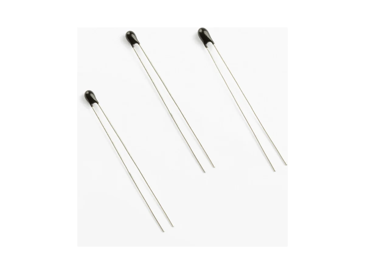
Leaded bead NTC thermistors for precision temperature measurement; R25 10–100 kΩ, B25/50 3,380 or 3,950 K, thermal time constant ≤7 s in static air.
Part-number list on request. Download the datasheet or send us your specification.
Send your specificationDatasheets, technical documents and approval certificates for this series. English editions of documents marked “Chinese” are available on request.
Leaded bead NTC thermistors for precision temperature measurement. Two constructions: 52A (A10) with tinned copper or tinned copper-clad steel leads, and 52B (B10) with enamelled wire. R25 10, 50 or 100 kΩ, B25/50 3,380 K or 3,950 K; thermal time constant ≤7 s in static air. Operating temperature −40 °C to +125 °C.
| Function | Leaded NTC bead thermistor for temperature measurement; zero-power resistance decreases as the element temperature rises |
|---|---|
| Constructions | Precision bead NTC in two constructions: 52A (A10) and 52B (B10) |
| R25 values | 10 kΩ · 50 kΩ · 100 kΩ |
| R25 tolerance | ±1% · ±2% · ±3% · ±5% · ±10% |
| R25 10 kΩ, B 3,380 K | B25/50 3,380 K · B25/85 3,435 K |
| R25 10 kΩ, B 3,950 K | B25/50 3,950 K · B25/85 4,000 K |
| R25 50 kΩ | B25/50 3,950 K · B25/85 4,000 K |
| R25 100 kΩ | B25/50 3,950 K · B25/85 4,000 K |
| B-value tolerance | ±1% · ±2% |
| B-value definition | B = ln(R1/R2) / (1/T1 − 1/T2) |
| B-value reference temperatures | B25/50: T1 = 298.15 K, T2 = 323.15 K · B25/85: T1 = 298.15 K, T2 = 358.15 K |
| Temperature accuracy | R25 and B tolerances do not state a ±°C accuracy. Calculate the temperature error from the R/T table. |
| Zero-power resistance | DC resistance at temperature t, measured at a power low enough that any further reduction changes the resistance by less than 0.1% |
| Operating temperature | −40 °C to +125 °C |
| Thermal time constant | ≤7 s in static air |
| Thermal time constant, definition | Time to reach 63.2% of the change from initial to final temperature, under zero-power conditions |
| Dissipation constant | ≥2.0 mW/°C in static air |
| Leads, 52A (A10) | Tinned copper wire or tinned copper-clad steel wire |
| Body, 52A (A10) | D max. 2.2 mm · L1 max. 3.5 mm |
| Lead dimensions, 52A (A10) | L2 ≥25.0 mm · d 0.35 ±0.05 mm · F 1.8 ±0.5 mm |
| Leads, 52B (B10) | Enamelled wire; conductor alloy and enamel thermal class on request |
| Body, 52B (B10) | D max. 2.0 mm · L1 max. 6.0 mm |
| Lead dimensions, 52B (B10) | L2 to customer specification · L3 3.0 ±1.0 mm · d 0.28 ±0.05 mm |
| Terminal option | 0 = without terminal · P = with terminal; terminal type and drawing on request |
| Lead length | Coded in the last four characters of the part number; 52A: L2 min. 25 mm; 52B: length to customer specification |
| Hand soldering and rework | 300 °C max. · 3 s max. · solder point at least 2 mm from the coating |
| Packing | Bulk |
| Storage | ≤35 °C · ≤70% RH · 12 months · keep the original package closed and reseal after opening; avoid corrosive atmospheres that degrade solderability |
| Environmental compliance | RoHS and REACH compliant; halogen status and material declarations on request |
| Liquid use | Validate immersion, fluid compatibility and insulation before use in liquids. |
| Automotive use | No AEC-Q200 qualification is specified for this series |
| Further data on request | R/T table · rated power, max. sensing current and voltage, allowed self-heating and derating versus ambient temperature · insulation resistance, dielectric withstand and body-to-lead isolation · coating material, flammability and moisture-barrier data · wave or reflow soldering, enamel stripping, lead forming, cleaning and potting compatibility · immersion and fluid-compatibility data · endurance, thermal-cycling, humidity, high- and low-temperature storage, vibration, shock, lead-strength and solderability results |
Ranges by dielectric, package and lead style within this series.
| Variant | Body dimensions | R25 / B25/50 | Thermal time constant / dissipation constant / temperature range | Lead / land pattern | Notes |
|---|---|---|---|---|---|
| 52A (A10) | D max. 2.2 mm · L1 max. 3.5 mm | 10 kΩ / 3,380 K · 10, 50, 100 kΩ / 3,950 K | τ ≤7 s · δ ≥2.0 mW/°C · −40 °C to +125 °C | L2 ≥25 mm · d 0.35 ±0.05 mm · F 1.8 ±0.5 mm · tinned copper or copper-clad steel | Compact bare-lead bead for PCB or assembly integration. Validate lead heat flow, coating and accuracy. |
| 52B (B10) | D max. 2.0 mm · L1 max. 6.0 mm | 10 kΩ / 3,380 K · 10, 50, 100 kΩ / 3,950 K | τ ≤7 s · δ ≥2.0 mW/°C · −40 °C to +125 °C | L2 to customer specification · L3 3 ±1 mm · d 0.28 ±0.05 mm · enamelled wire | Enamelled-wire construction for custom lead length. Validate enamel class, termination and strain relief. |
Start with the temperature and error window. Then choose one of the four R25/B combinations and the A or B lead construction, and verify self-heating, thermal response, coating and fluid compatibility, process and qualification for the selected part number.
Set the mission profile within −40 °C to +125 °C, the required ±°C accuracy, response, drift, calibration, airflow or liquid exposure, mechanical load and application qualification.
Select 10 kΩ / 3,380 K or 10, 50 or 100 kΩ / 3,950 K for the circuit resolution. R/T table and tolerance band on request.
Use 52A for tinned bare leads and a body length of max. 3.5 mm, or 52B for enamelled wire and customer-specified length. Validate lead heat flow, insulation, termination and mechanical integration.
Calculate max. voltage, current, power and self-heating across the curve. Correlate the ≤7 s static-air value with the actual PCB, potting, fluid, contact or enclosure thermal path.
Specify coating and lead materials, body and lead drawing, terminal and length, soldering or enamel process, packing, environmental declarations, drift and application-specific reliability for the selected part number.
MF52 is specified at 10 kΩ / 3,380 K and at 10, 50 and 100 kΩ / 3,950 K. Other values on request.
Build the temperature error budget from R/T tolerance, ADC, reference and divider error, self-heating, thermal gradients, calibration and drift at every critical temperature.
Copper, copper-clad steel and enamelled wire differ in heat conduction, insulation and termination. Validate the complete lead path; do not assume identical response or object-temperature tracking.
Before use in liquids, validate coating, insulation under bias, potting cure, moisture ingress and response in the actual medium.
Avoid bending, clamping or pulling at the coated body. Use controlled lead forming, board support, strain relief and solder or enamel termination so that assembly stress does not alter resistance or crack the coating.
Battery and automotive applications need mission-profile temperature, electrical isolation, flame and fault behavior, vibration, humidity, change control and application-specific qualification.
Example ordering code. Not every combination is available.
MT · 52A · 103 · F · 3950 · F · 0 · 0000
| Code | Meaning |
|---|---|
| MT | Temperature-sensing NTC prefix |
| 52A | Construction: 52A (A10) or 52B (B10) |
| 103 | R25: 103 = 10 kΩ, 104 = 100 kΩ; available 10, 50 and 100 kΩ |
| F | R25 tolerance: F = ±1%; G ±2%, H ±3%, J ±5%, K ±10% |
| 3950 | Nominal B25/50: 3950 = 3,950 K; 3380 = 3,380 K (B25/85 4,000 K and 3,435 K) |
| F | B-value tolerance: F = ±1%; G = ±2% |
| 0 | Terminal: 0 = without terminal; P = with terminal |
| 0000 | Lead length: 52A min. 25 mm, 52B to customer specification; code table on request |