CE

CE Series Safety Certified Disc Ceramic Capacitors (Class X1/Y2)

Safety classX1 / Y2 (IEC 60384-14)
Rated voltageX1 440 VAC · Y2 300 VAC · 1,500 VDC (Annex H)
Capacitance100–10,000 pF
Humidity robustnessAnnex I grade IIIB
Lead spacing7.5 / 10.0 mm
ApprovalsCQC · VDE/ENEC · IECEE CB · UL/cUL
UL certification markVDE certification markENEC certification markCQC certification mark

Leaded disc ceramic safety capacitors, Class X1/Y2 to IEC 60384-14. X1 up to 440 VAC, Y2 up to 300 VAC, 100–10,000 pF.

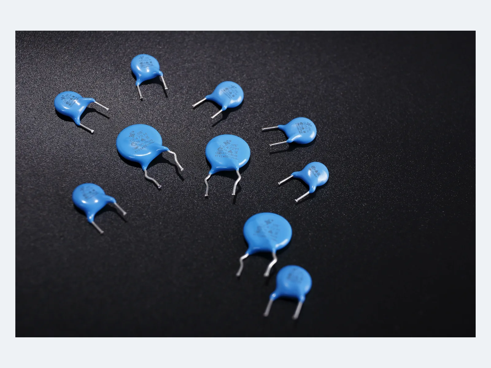
Series product photograph

Part numbers

657

Showing 25 of 657 part numbers

G06B1E221KN0B0S0NS
G06B1E471KN0B0S0NS
G06B1E471KQ0T0S0NS
G06B2E471KA0B2S0NS
G06B2E471KA5B0S0NS
G06B3E471KA5B0S0NS
G06E1D102MN0B0S0NS
G06E1E102MN0B0S0NS
G06E1E102MQ0T0S0NS
G06E2E102MA5B0S0NS
G06E2E102MP0T0S0PS
G06E3E102MA2B0S0NS
G06E3E102MA5B0S0NS
G06E8E102MP0T0S0PS
G06F1E102MN0B0S0NS
G06F1E102MQ0T0S0PS
G06F2E102MA4B0S0NS
G06F2E102MA5B0S0NS
G06F2E102MP0T0S0PS
G06F3E102MA2B0S0NS
G06F3E102MA5B0S0NS
G06F3E102MC2B0S0NS
G06F3E102MD0B0S0NS
G06F3E102MD5B0S0NS
G06F8E102MP0T0S0PS

Need a value that is not listed? Send us your specification.

Engineering details

Overview

Leaded disc ceramic safety capacitors, Class X1/Y2 to IEC 60384-14, for line filtering and line-to-earth EMI suppression across basic insulation. X1 up to 440 VAC, Y2 up to 300 VAC, 100–10,000 pF. Designated constructions are certified for 1,500 VDC. Annex I grade IIIB: 1,000 h at 85 °C / 85% RH with rated voltage.

Series features

  • Class X1/Y2 to IEC 60384-14 for across-the-line and basic/supplementary-insulation positions
  • X1 440/400 VAC and Y2 300/275/250 VAC within the approval scope
  • Dielectrics Y5P, Y5U and Y5V, 100–10,000 pF
  • 1,500 VDC (Annex H) and humidity robustness grade IIIB (Annex I)
  • Lead spacing 7.5 or 10.0 mm; radial epoxy-coated construction up to +125 °C
Specifications
Safety classX1 / Y2 · IEC 60384-14
Insulation functionY2: basic or supplementary insulation · not a Y1 substitute
Rated voltage, X1440 · 400 VAC
Rated voltage, Y2300 · 275 · 250 VAC
Rated DC voltage1,500 VDC · designated constructions (Annex H)
Capacitance range100–10,000 pF
Certified capacitance by dielectricY5P 100–1,000 pF · Y5U 680–10,000 pF · Y5V 1,000–10,000 pF
Standard part rangeY5P 100–680 pF · Y5U 680–10,000 pF · Y5V 1,500–10,000 pF
Capacitance toleranceK ±10% · M ±20%, depending on dielectric and value
Operating temperature−40 °C to +125 °C
Climatic category40/125/21
Humidity robustnessAnnex I grade IIIB · 1,000 h at 85 °C / 85% RH with rated voltage
Passive flammabilityClass B
Measuring conditions25 °C · 1 kHz · 1 Vrms
Dissipation factor≤2.5%
Insulation resistance≥10,000 MΩ
Dielectric strength2,600 VAC · increased proof-test level (CB Test A)
Lead spacing7.5 ±0.8 mm · 10.0 ±0.8 mm for selected large values
Lead diameter0.60 or 0.65 ±0.05 mm, depending on part
Body dimensionsD max. 7.0–18.0 mm · T max. 4.0–4.5 mm
Hand soldering350 °C max. · 3 s max. · ≥2 mm from coating
Storage≤35 °C · ≤70% RH · 12 months, unopened
Environmental complianceRoHS · REACH · bromine-free / halogen-free
Variants

Ranges by dielectric, package and lead style within this series.

VariantBody dimensionsCapacitance rangeTolerance / approval scopeLead / land patternNotes
Y5PD max. 7.0–8.5 · T max. 4.0 mm (standard parts)100–1,000 pF certified · 100–680 pF standardK ±10% · 1,500 VDC · IIIBF 7.5 ±0.8 · d 0.60 mmLower-capacitance EMI and coupling paths; 820 pF and 1 nF on request.
Y5UD max. 7.0–18.0 · T max. 4.0–4.5 mm680–10,000 pFK ±10% or M ±20% · 1,500 VDC · IIIBF 7.5 ±0.8; 10.0 ±0.8 for selected 4.7/10 nF parts · d 0.60/0.65 mmWidest CE capacitance range, up to 10 nF.
Y5VD max. 7.0–14.0 · T max. 4.0–4.5 mm1,000–10,000 pF certified · 1,500–10,000 pF standardM ±20% · 1,500 VDC · IIIBF 7.5 ±0.8; 10.0 ±0.8 for selected 10 nF parts · d 0.60/0.65 mmCompact high-capacitance range; check effective capacitance and leakage-current margin closely.
Selection guide

Y2 is a basic or supplementary insulation class, not a Y1 equivalent. Define the circuit position first. Then match X1/Y2 AC duty, the 1,500 VDC scope, leakage current, dielectric behavior, lead spacing and approval code.

  1. Classify X1 or Y2 duty

    Use X1 for across-the-line suppression. Use Y2 line-to-earth only where the end-equipment standard permits basic or supplementary insulation. Do not use CE where reinforced (Y1) insulation is required.

  2. Define AC, DC and transient voltage

    Select the X1 440/400 VAC or Y2 300/275/250 VAC combination. 1,500 VDC applies to designated Annex H constructions; impulse data on request. The 2.6 kVAC proof test is not a continuous or surge rating.

  3. Choose capacitance and dielectric

    Certified and standard ranges differ at the range limits. Select an orderable Y5P/Y5U/Y5V part, then check temperature and voltage dependence and tolerance before using nominal capacitance in the EMI model.

  4. Close the leakage-current budget

    For line-to-earth use, calculate I = 2πfCV at maximum voltage, frequency and tolerance. Check the result against equipment touch-current limits and the number of Y capacitors in the system.

  5. Confirm geometry, process and approvals

    Choose 7.5 or 10 mm lead spacing, then specify body and lead dimensions, packaging and approval marking for the final part number.

Approvals & reliability

Approvals & qualifications

CE X1/Y2 is certified by CQC, VDE/ENEC and IECEE CB and recognized by UL/cUL.

AgencyStandardCertificateScope
CQC certification markCQCGB/T 6346.14-2023CQC19001213202CE X1/Y2, 100–10,000 pF; X1 440/400 VAC, Y2 300/275/250 VAC; Y5P/Y5U/Y5V, tolerance K/M, 40/125/21/B; Annex H 1,500 VDC; Annex I grade IIIB. Issued 15 Nov 2023, valid subject to surveillance.
VDE certification markENEC certification markVDE / ENECEN 60384-1440025748CE series, 100–10,000 pF; X1 440/400 VAC, Y2 300/275/250 VAC; Y5P/Y5U/Y5V, 40/125/21, class B; Annex H 1,500 VDC; Annex I grade IIIB.
IECEE CB scheme markIECEE CBIEC 60384-14:2013 + AMD1:2016DE1-67721/B2CE series, 100–10,000 pF, X1 400/440 VAC, Y2 250/275/300 VAC, 40/125/21/B; Annex H 1,500 VDC; Annex I grade IIIB; voltage proof Test A at 2,600 VAC. Issued 9 Aug 2023.
UL certification markUL / cULANSI/UL 60384-14 / CAN/CSA-E60384-14E208107Recognized component, USA and Canada: CE X1/Y2, 100–10,000 pF, X1 400/440 VAC, Y2 250/275/300 VAC, 1,500 VDC, −40 to +125 °C, tolerance K/M, grade IIIB.

Each certificate covers the types and ratings listed on it.

Reliability tests

CE is certified to Annex I grade IIIB, with the voltage proof test at 2.6 kVAC. Impulse, endurance and post-test acceptance data on request.

TestConditionAcceptance
Humidity robustness, Annex I85 °C / 85% RH · rated voltage · 1,000 hGrade IIIB (certified).
Voltage proof, Test A2,600 VAC, increased test voltage (CB certificate DE1-67721/B2)Approval test. Production-test duration, ramp, trip current and conditioning on request.
Design notes

Y2 is not reinforced insulation

Use CE line-to-earth only where the equipment standard permits Y2 basic or supplementary insulation. Do not replace a CY or CD Y1 capacitor in a reinforced-insulation position because capacitance, voltage or footprint appear to match.

Continuous, proof and impulse voltage differ

The series has rated AC/DC voltages and a 2.6 kVAC proof test. These are different quantities. Impulse waveform and repetitive-transient limits for the actual mains and switching environment are available on request.

Values at the range limits

Approvals cover Y5P up to 1 nF and Y5V from 1 nF. Standard parts cover Y5P up to 680 pF and Y5V from 1.5 nF. Values in between: availability, body size and part code on request.

Leakage current adds up across Y capacitors

Calculate 2πfCV at maximum mains frequency, voltage and tolerance for each line-to-earth capacitor, then total the complete network. Keep margin for the temperature and voltage dependence of the dielectric and for touch-current limits.

Grade IIIB is a test classification

CE is certified to Annex I grade IIIB (1,000 h at 85 °C / 85% RH). The grade is not a lifetime rating.

Soldering, lead stress and storage

Hand rework: 350 °C max., 3 s max., at least 2 mm from the coating. Store unopened parts for up to 12 months at ≤35 °C / ≤70% RH, away from corrosive gases. Form and support leads without loading the ceramic body.

Part numbering

Example ordering code. Not every combination is available.

G · 08 · F · 1 · E · 222 · M · N0 · B · 0 · H · 0 · N · 0

CodeMeaning
GRated-voltage family code (Y2)
08Body diameter code: 08 = 8 mm
FTemperature characteristic: F = Y5V
1Lead form: 1 = long straight leads
ELead spacing: E = 7.5 mm, D = 10.0 mm
222Capacitance code: 222 = 2,200 pF
MCapacitance tolerance: M ±20%
N0Lead length or tape seating-height code, depending on packaging
BPackaging: B = bulk, T = tape
0Environmental code: 0 = RoHS; a RoHS + halogen-free code is also defined
HApproval voltage code: H = X1 440 VAC / Y2 300 VAC
0 · N · 0Internal management codes