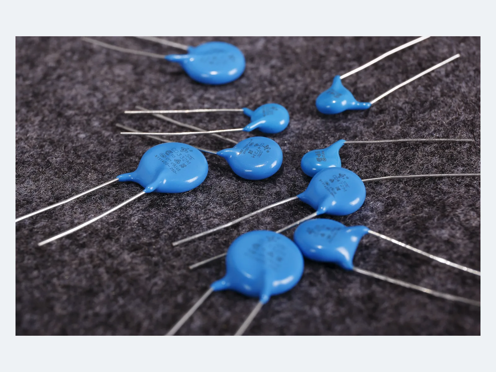
Start from the circuit position and insulation requirement in the equipment standard. Then define AC/DC voltage, impulse duty, leakage current (set by capacitance), dielectric behavior and approval scope. A dual X1/Y1 marking does not replace qualification of the ordered part in its operating environment.
- 01
Classify the circuit position
Identify line-to-line, line-to-earth or primary-to-secondary use from the end-equipment standard. Y1 bridges reinforced insulation; the insulation diagram and overvoltage category of the equipment govern the choice.
- 02
Define AC, DC and impulse duty
Choose the X1 and Y1 voltage combination, then include repetitive peaks and abnormal transients. The 1,500 VDC approval applies only to designated Y5U/Y5V constructions, not to Y5P.
- 03
Set the capacitance limit from leakage current
Calculate line-frequency current and touch/leakage current at maximum mains voltage and frequency, including tolerance. Use the lowest capacitance that meets the common-mode attenuation target.
- 04
Choose dielectric and tolerance
Y5P, Y5U and Y5V cover different value ranges and temperature characteristics. Data on capacitance versus temperature, voltage and frequency is available on request when the circuit depends on effective rather than nominal capacitance.
- 05
Confirm mechanical and approval codes
Confirm disc diameter, thickness, lead diameter, lead form, bulk or tape packaging, environmental code and approvals for the final part number before PCB and BOM release.