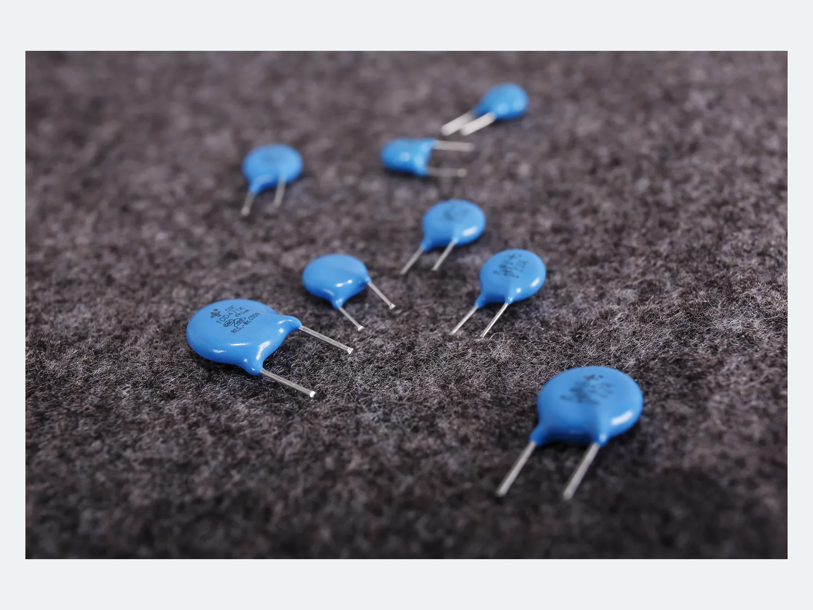
| Function | Radial-leaded zinc-oxide varistor for transient voltage clamping; voltage-dependent shunt element with finite pulse life |
|---|
| Construction | Epoxy-coated zinc-oxide disc with radial leads |
|---|
| Reference standards | GB/T 10193 · GB/T 10194 · GB 8898-2011 · GB 4943.1-2011 · UL 1449 · IEC 61051 · IEC 60950-1:2013 |
|---|
| Disc sizes | 05D · 07D · 10D · 14D · 20D |
|---|
| Nominal varistor voltage | 18–680 V (05D) · 18–820 V (07D) · 18–1,100 V (10D, 14D, 20D) |
|---|
| Max. continuous voltage | 11–680 VAC · 14–895 VDC; per disc size and voltage code |
|---|
| Varistor voltage measured at | 0.1 mA (05D) · 1 mA (07D, 10D, 14D, 20D) |
|---|
| Varistor-voltage tolerance | K = ±10%. Some low-voltage types have asymmetric limits (see datasheet). |
|---|
| Max. clamping voltage | Specified per part number at test current IP. Compare clamping voltages only at the same current and waveform. |
|---|
| Max. peak current, 8/20 µs, one pulse | 100–6,500 A; per disc size and voltage code |
|---|
| Max. peak current, 8/20 µs, two pulses | 50–4,500 A. Not a repetitive-pulse rating. |
|---|
| Max. energy absorption, 10/1000 µs | 0.4–383 J; per part number |
|---|
| Rated power | 0.01–1.0 W, depending on disc size and voltage |
|---|
| Capacitance (typical) | 38–28,500 pF at 1 kHz |
|---|
| Waveform ratings | 8/20 µs current and 10/1000 µs energy ratings are separate tests. Do not convert either to another waveform or to repetitive duty. |
|---|
| Operating temperature | −40 °C to +105 °C |
|---|
| Storage | ≤35 °C · ≤70% RH · no corrosive gas or direct sunlight · 12 months max. |
|---|
| Dimensions, 05D | D max. 7.5 mm · T max. 3.5–5.5 mm · lead pitch F 5.0 ±0.5 mm · lead Ø d 0.5 ±0.05 mm |
|---|
| Dimensions, 07D | D max. 9.0 mm · T max. 3.5–5.5 mm · lead pitch F 5.0 ±0.5 mm · lead Ø d 0.5 ±0.05 mm |
|---|
| Dimensions, 10D | D max. 12.5 mm · T max. 4.0–7.5 mm · lead pitch F 7.5 ±0.5 mm · lead Ø d 0.7 ±0.05 mm |
|---|
| Dimensions, 14D | D max. 16.0 mm · T max. 4.0–7.5 mm · lead pitch F 7.5 ±0.5 mm · lead Ø d 0.7 ±0.05 mm |
|---|
| Dimensions, 20D | D max. 23 mm (18–68 V), 21 mm (from 82 V) · T 4.0–8.0 mm · lead pitch F 10 ±0.5 mm · lead Ø d 1.0 mm straight / 0.8 mm bent, ±0.05 mm |
|---|
| Lead forms | Long straight · single outward bend · short straight · front/rear raised |
|---|
| Lead length | Long straight ≥16 mm; short or bent 2.5–<6 mm ±0.5 mm or 6–10 mm ±1.0 mm. Coating run-down and bend height depend on the lead form. |
|---|
| Packing | Bulk or taped; taping for 5, 7.5 and 10 mm lead pitch |
|---|
| Taping | Component pitch 12.7 or 25.4 mm, depending on lead pitch · carrier width 18 mm · H0 16.5 / 17 / 19 / 20 mm |
|---|
| Hand soldering and rework | 350 °C max. · 3 s max. · solder point at least 2 mm from the coating |
|---|
| Flame class | Class C per CQC approval, for covered constructions |
|---|
| End-of-life protection | Leakage current and clamping voltage can change after surges. Coordinate upstream overcurrent protection or a thermal disconnector. |
|---|
| Further data | On request: rated-power derating versus ambient temperature · peak-current and energy derating versus pulse count, pulse width and interval · wave-soldering, preheat, cleaning and conformal-coating conditions · failure-mode data · endurance, damp-heat, thermal-cycling, vibration, lead-strength and solderability results |
|---|