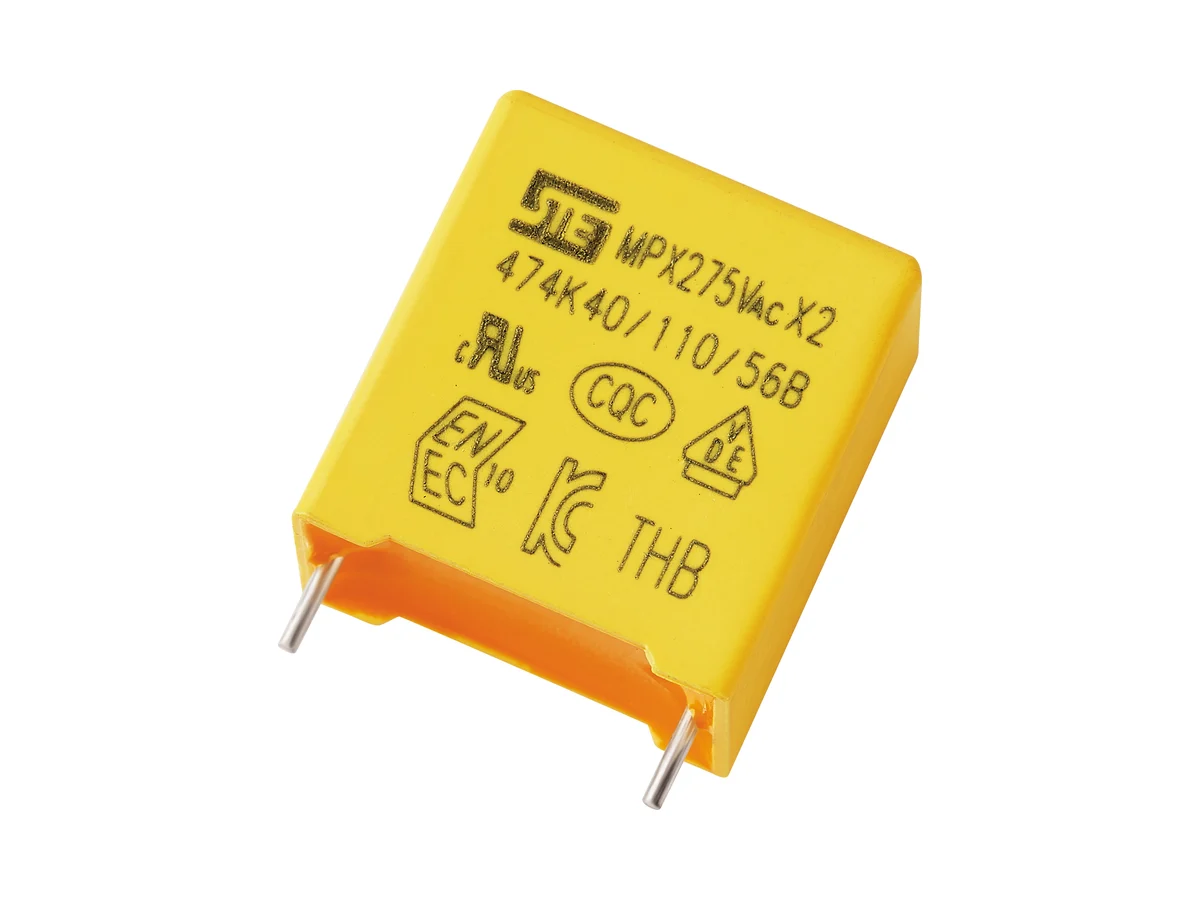
MPX/X2-THB

MPX/X2-THB Series Metallized Polypropylene Film Interference Suppression Capacitors (Class X2, THB)

Safety classX2, across-the-line
THB test85 °C / 85% RH · 240 VAC · 500 h
Rated voltage275 / 305 / 310 / 330 / 350 VAC
Capacitance0.001–10 µF
Tolerance±10%
Operating temperature−40 °C to +110 °C
CQC certification markVDE certification markENEC certification markcRUus recognized component markKTL organization logoKC certification mark

Boxed metallized polypropylene film capacitors for across-the-line EMI suppression in humid environments, Class X2. Rated 275–350 VAC, 1 nF–10 µF.

Series product photograph

Part numbers

288

Showing 25 of 288 part numbers

X2P2102KN1A5130110050ES80.001±10275X2
X2P2102KN1B0130110050ES80.001±10275X2
X2Q3102KJ135100090040ES80.001±10310X2
X2Q3102KJ1B0100090040ES80.001±10310X2
X2Q3102KN1B0130090040ES80.001±10310X2
X2Q3122KJ1B0100090040ES80.0012±10310X2
X2Q3122KN1B0130090040ES80.0012±10310X2
X2Q3152KJ1B0100090040ES80.0015±10310X2
X2Q3152KN1B0130090040ES80.0015±10310X2
X2Q3182KJ1B0100090040ES80.0018±10310X2
X2Q3182KN1B0130110050ES80.0018±10310X2
X2Q3222KJ135100110050ES80.0022±10310X2
X2Q3222KJ1B0100090040ES80.0022±10310X2
X2Q3222KJ1B0100110050ES80.0022±10310X2
X2Q3222KN1B0130110050ES80.0022±10310X2
X2Q3272KJ1B0100090040ES80.0027±10310X2
X2Q3272KN1B0130110050ES80.0027±10310X2
X2Q3332KJ1B0100090040ES80.0033±10310X2
X2Q3332KN1B0130110050ES80.0033±10310X2
X2Q3392KJ1B0100090040ES80.0039±10310X2
X2Q3392KN1B0130110050ES80.0039±10310X2
X2Q3472KJ1B0100090040ES80.0047±10310X2
X2Q3472KN1B0130110050ES80.0047±10310X2
X2Q3562KJ1B0100090040ES80.0056±10310X2
X2Q3562KN1B0130110050ES80.0056±10310X2

— = not specified

Need a value that is not listed? Send us your specification.

Engineering details

Overview

Self-healing, boxed metallized polypropylene film capacitors for across-the-line (L–N) EMI suppression in humid environments, Class X2 to IEC / EN / UL 60384-14. Rated 275, 305, 310, 330 and 350 VAC; 1 nF–10 µF; tolerance ±10%. Biased humidity test: 85 °C / 85% RH, 240 VAC, 500 h, |ΔC/C| ≤10%. Climatic category 40/110/56.

Series features

  • Class X2 to IEC / EN / UL 60384-14 for across-the-line (L–N) interference suppression
  • Self-healing metallized polypropylene winding
  • Five AC ratings: 275, 305, 310, 330 and 350 VAC; certified range 1 nF–10 µF
  • THB test: 500 h at 85 °C / 85% RH and 240 VAC, |ΔC/C| ≤10%
  • Flame-retardant box to UL 94 V-0 with moisture-resistant resin fill
Specifications
Safety functionClass X2 · across-the-line (L–N) interference suppression · not for line-to-earth (Y) positions
ConstructionNon-inductive metallized polypropylene film · boxed, resin-encapsulated · self-healing
Reference standardsIEC / EN / UL 60384-14 · GB/T 6346.14-2023 · K 60384
Rated AC voltage UR275 · 305 · 310 · 330 · 350 VAC
Capacitance range0.001–10 µF · available values depend on rated voltage, body size and approval scope
Capacitance tolerance±10% (K)
Operating temperature−40 °C to +110 °C
Climatic category40/110/56
Passive flammabilityCategory B (VDE) · case and resin to UL 94 V-0
Dissipation factortan δ ≤0.1%
Insulation resistance, CR ≤0.33 µF≥15,000 MΩ at 20 °C, 100 VDC, 60 s
Insulation resistance, CR >0.33 µFTime constant ≥5,000 s (T = IR [MΩ] × CN [µF]) at 20 °C, 100 VDC, 60 s
Voltage proof, terminal to terminal4.3 × UR DC, 5 s
Voltage proof, terminals to case2 × UR + 1,500 VAC, min. 2,000 VAC
Biased humidity test (THB)85 ±2 °C · 85 ±2% RH · 240 VAC · 500 h
THB acceptance|ΔC/C| ≤10%; other post-test limits on request
IEC 60384-14 Annex I gradeNone: VDE certificate 40034679 includes no Annex I humidity-robustness grade. The 500 h THB test is an STE test, not a certified grade.
DC operationNo continuous DC rating; the VDE approval includes no Annex H (DC) approval
Body widthW 10–42.5 mm, depending on rated voltage and capacitance
Body heightH 9–50 mm, depending on rated voltage and capacitance
Body thicknessT 4–35 mm, depending on rated voltage and capacitance
Lead pitch7.5 · 10 · 12.5 · 15 · 22.5 · 27.5 · 37.5 mm
Lead diameter0.6 mm (pitch 7.5–12.5 mm) · 0.8 mm (15–27.5 mm) · 1.0 mm (37.5 mm)
Lead and packing formsLong straight · inner-bent · straight, taped · bent, taped · bulk or radial tape
Taped seating height HH = 20.0 ±1.0 mm
Hand soldering / reworkIron ≤350 °C · ≤3 s · ≥2 mm from the coating
Reflow solderingNot permitted; film shrinkage can degrade performance
StorageIn unopened package: ≤35 °C, ≤70% RH, ≤12 months. Keep away from corrosive gases to preserve lead solderability.
Environmental codingE = RoHS · F = RoHS + halogen-free
Further dataOn request: tan δ measurement conditions; dV/dt, peak and RMS current, ESR/impedance, self-heating and permissible overvoltage; dry-heat endurance, pulse count, thermal cycling, vibration and lead strength
Variants

Ranges by dielectric, package and lead style within this series.

VariantBody dimensionsRated voltage / capacitanceConstruction / classLead / land patternNotes
J · 7.5 mmW 10 · H 9–15 · T 4–8 mm275–350 VAC · 0.001–0.033 µFMetallized PP · X2 · K ±10%P 7.5 ±0.5 · d 0.6 ±0.05 mmLow capacitance values at minimum pitch. 330 and 350 VAC parts generally use a taller or thicker case.
N · 10 mmW 13 · H 9–15.5 · T 4–8 mm275–350 VAC · 0.001–0.15 µFMetallized PP · X2 · K ±10%P 10 ±0.5 · d 0.6 ±0.05 mmCompact range up to 0.15 µF; case size increases with rated voltage.
P · 12.5 mmW 15 · H 12.5–15 · T 7–9 mm275–350 VAC · 0.15–0.22 µFMetallized PP · X2 · K ±10%P 12.5 ±0.5 · d 0.6 ±0.05 mmAvailability on request.
Q · 15 mmW 18 · H 11–20 · T 5–11 mm275–350 VAC · 0.01–0.56 µFMetallized PP · X2 · K ±10%P 15 ±0.5 · d 0.8 ±0.05 mmMain pitch for mid-range values. The same capacitance can come in different case and lead versions, identified by the full part number.
T · 22.5 mmW 26.5 · H 16–22 · T 7–13 mm275–350 VAC · 0.15–0.82 µFMetallized PP · X2 · K ±10%P 22.5 ±0.5 · d 0.8 ±0.05 mmLarger case for higher capacitance, all five voltage ratings.
V · 27.5 mmW 31–32 · H 20–37 · T 11–22 mm275–310 VAC to 3.9 µF · 330/350 VAC to 3.3 µFMetallized PP · X2 · K ±10%P 27.5 ±0.5 · d 0.8 ±0.05 mmHigh capacitance; the upper limit and case size depend on rated voltage.
L · 37.5 mmW 41–42.5 · H 28–50 · T 14–35 mm275–350 VAC · 2–10 µFMetallized PP · X2 · K ±10%P 37.5 ±0.5 · d 1.0 ±0.05 mmLargest case. For high-energy filter or dropper duty, verify RMS current, temperature rise, inrush and the discharge path.
Selection guide

Begin with the circuit position and the required X2 approval. Then select AC voltage, capacitance, humidity profile and pitch together. The 500 h THB test is an STE test; the VDE approval includes no IEC 60384-14 Annex I humidity grade.

  1. Confirm the X2 circuit position

    Use this series across line conductors for differential-mode suppression or in a capacitive supply approved for the equipment. It is not a Y capacitor and does not provide reinforced line-to-earth insulation.

  2. Select the rated AC voltage and check mains disturbances

    Choose 275, 305, 310, 330 or 350 VAC for the approved capacitance and body combination. Check mains tolerance, transients, repetitive pulses and the overvoltage requirements of the equipment standard. The 4.3 × UR proof test is a test condition, not a continuous operating margin.

  3. Determine capacitance, losses and current

    Size the filter or dropper using tolerance, tan δ, frequency, RMS current and self-heating. Only an initial tan δ limit is specified; dV/dt, current and ESR data for high-current duty are available on request.

  4. Match the THB test to the mission profile

    The THB test is 500 h at 85 °C / 85% RH and 240 VAC with |ΔC/C| ≤10%. Post-test tan δ and IR data and field-life correlation are available on request. Do not specify it as IEC grade IIB: certificate 40034679 includes no Annex I grade.

  5. Specify case, pitch and process

    Specify W/H/T, pitch, lead diameter and form and packaging for each capacitance and voltage. Validate wave and hand soldering, cleaning, coating, storage and PCB creepage. Do not reflow-solder.

Approvals & reliability

Approvals & qualifications

Approvals cover 1 nF–10 µF at 275–350 VAC. The VDE approval includes neither an Annex H (DC) approval nor an Annex I humidity-robustness grade.

AgencyStandardCertificateScope
CQC certification markCQCGB/T 6346.14-2023CQC19001213200MPX X2, 0.001–10 µF, 275/305/310/330/350 VAC, ±10% (certificate dated 14 Nov 2023).
VDE certification markENEC certification markVDE / ENECEN 60384-14:201740034679MPX X2, 0.001–10 µF, 275/305/310/330/350 VAC, ±10% (K), 40/110/56, passive flammability category B. No Annex H (DC) approval; no Annex I humidity grade.
cRUus recognized component markUL / cULUL 60384-14E208107MPX X2, 0.001–10 µF, 275/305/310/330/350 VAC, ±10%, −40 to +110 °C.
KTL organization logoKC certification markKTL / KCK 60384SU03031 familyCertificates SU03031-12001C, -12002C, -12003D, -12004D, -23001 and -23002 cover six capacitance bands up to 10 µF. Certificate copies on request.

Each certificate covers the types and ratings listed on it.

Reliability tests

Initial electrical characteristics and one biased damp-heat test (500 h) are specified. IEC 60384-14 endurance and impulse test data on request.

TestConditionAcceptance
Biased damp heat (THB)85 ±2 °C · 85 ±2% RH · 240 VAC · 500 h|ΔC/C| ≤10%; tan δ, IR, voltage-proof, visual and sample-size criteria on request
Voltage proof, terminal to terminal4.3 × UR DC, 5 sRamp rate, trip current, repeat-test rule and post-test limits on request
Voltage proof, terminals to case2 × UR + 1,500 VAC, min. 2,000 VACTest duration, electrode method and trip current by case size on request
Initial dissipation factor and insulation resistancetan δ ≤0.1%; IR ≥15,000 MΩ (CR ≤0.33 µF) or time constant ≥5,000 s (CR >0.33 µF)IR measured at 100 VDC, 60 s
Design notes

X2 is an across-the-line safety function

Use X2 between supply conductors for differential-mode interference suppression. Line-to-earth positions require the correct Y class; do not infer an insulation function from the box style or the high proof voltage.

Voltage rating is part-specific

The series covers 275–350 VAC, but case size, capacitance and approval marking must match the ordered part number. Select for mains tolerance and the impulse category of the equipment standard, not nominal line voltage alone.

Check current and pulse load

A filter or capacitive dropper sees continuous RMS current, switching pulses, inrush and self-heating. Request dV/dt, peak-current, ESR/impedance and temperature-rise data for the actual waveform.

THB test is not a lifetime rating

The THB test is 500 h at 85 °C / 85% RH and 240 VAC with a capacitance-change limit. The VDE certificate includes no Annex I grade. Lifetime estimates need the full qualification report and the application mission profile.

Design the discharge and failure path

Across-the-line capacitance affects stored energy, touch-safe discharge time and leakage and current budgets. Coordinate the bleeder network, fusing and open- and short-circuit failure analysis with the equipment safety standard.

Protect the film construction during assembly

Use the specified wave- or hand-soldering profile, keep the iron at least 2 mm from the case and do not reflow-solder. Validate cleaning, conformal coating, lead forming, PCB spacing and storage away from corrosive gases.

Part numbering

Example ordering code. Not every combination is available.

X2 · P2 · 104 · K · Q · 1 · B0 · 180 · 120 · 060 · E · S · 8

CodeMeaning
X2Safety class X2 and series
P2Rated voltage: P2 = 275 VAC; Q2 = 305, Q3 = 310, R1 = 330, R2 = 350 VAC
104Capacitance code: 104 = 100 nF
KCapacitance tolerance: K = ±10%
QLead pitch: Q = 15 mm; J = 7.5, N = 10, P = 12.5, T = 22.5, V = 27.5, L = 37.5 mm
1Lead form: 1 = long straight; 2 = inner-bent, 5 = straight taped, 6 = bent taped
B0Lead length: B0 = 20.0 mm (codes B0–B9)
180Body width: 180 = 18.0 mm
120Body height: 120 = 12.0 mm
060Body thickness: 060 = 6.0 mm
EEnvironmental: E = RoHS; F = RoHS + halogen-free
SCase color: S = yellow; E = gray
8STE internal management code