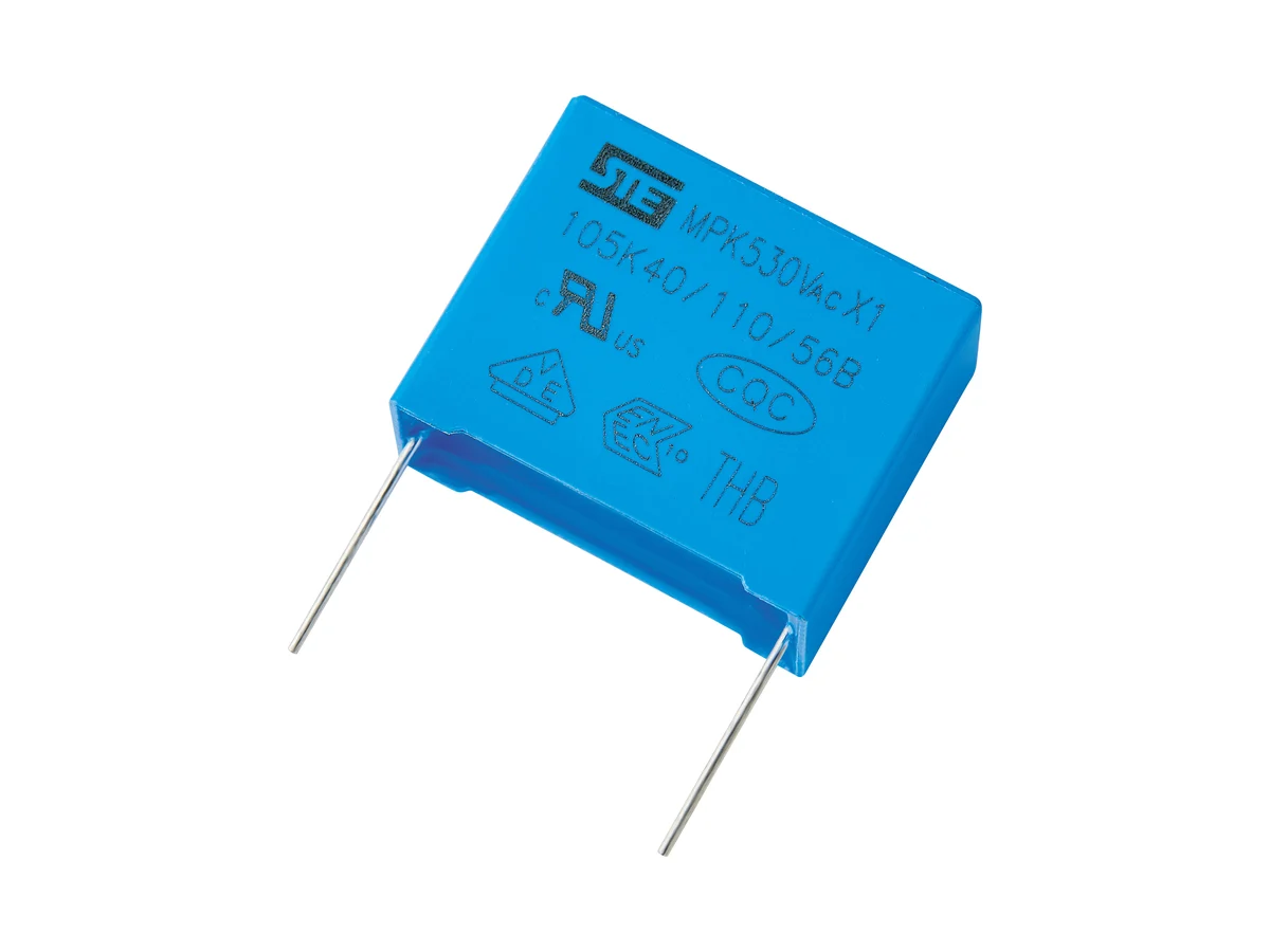
MPK/X1-AAEC-Q200

Automotive MPK/X1 Series Metallized Polypropylene Film Interference Suppression Capacitors (Class X1, AEC-Q200)

Safety classX1, across-the-line
Automotive qualificationAEC-Q200 Rev E qualified part numbers available
Rated voltage330 / 440 / 480 / 500 / 530 VAC
Capacitance0.001–1.0 µF
Impulse test voltage4 kV (CR ≤1.0 µF)
Temperature cycling1,000 cycles, −55 °C to +110 °C
UL certification markVDE certification markENEC certification markCQC certification markIECEE CB scheme mark

Automotive boxed metallized polypropylene film capacitors, Class X1, for across-the-line EMI suppression. AEC-Q200 Rev E qualified part numbers available; 330–530 VAC; 1 nF–1 µF.

Series product photograph

Part numbers

5

Showing 5 of 5 part numbers

X1S3102KN1A5130110050EVG0.001±10480X1
X1S1224KT1B5260200110EVG0.22±10440X1
X1S1224KT1B5260200110EVG-020.22±10440X1
X1S1684KV135310280140EVG0.68±10440X1
X1S1684KV135310280140EVG-020.68±10440X1

— = not specified

Need a value that is not listed? Send us your specification.

Engineering details

Overview

Automotive boxed metallized polypropylene film capacitors for across-the-line (L–N) EMI suppression, Class X1 to IEC 60384-14 for higher impulse stress. AEC-Q200 Rev E qualified part numbers available; temperature cycling 1,000 cycles, −55 °C to +110 °C. Rated 330, 440, 480, 500 and 530 VAC; 1 nF–1 µF; tolerance ±10% or ±20%. Impulse test voltage 4 kV (CR ≤1.0 µF). Climatic category 40/110/56B.

Series features

  • Class X1 metallized polypropylene construction for differential-mode mains suppression under higher impulse stress
  • Rated 330, 440, 480, 500 and 530 VAC; 1 nF–1 µF
  • AEC-Q200 Rev E qualified part numbers available; 1,000 temperature cycles from −55 °C to +110 °C
  • Impulse test (4 kV, 24 pulses) and self-ignition test are specified
  • Automotive parts carry the suffix G in the part number
Specifications
Product roleAutomotive Class X1 across-the-line (L–N) interference-suppression capacitor
ConstructionBoxed metallized polypropylene film
Safety functionClass X1 to IEC 60384-14 for the higher-impulse across-the-line category · not for line-to-earth (Y) or reinforced-insulation positions
Automotive qualificationAEC-Q200 Rev E qualified part numbers available; qualification report and temperature grade on request
Temperature cycling1,000 cycles, −55 °C to +110 °C
Climatic category40/110/56B (lower category temperature −40 °C; −55 °C is a temperature-cycling test condition)
Operating temperatureUpper category temperature +110 °C
Rated AC voltages330 · 440 · 480 · 500 · 530 VAC
Capacitance range0.001–1.0 µF; available values depend on rated voltage and pitch
Capacitance tolerance±10% (K) · ±20% (M)
Dissipation factortan δ ≤0.1%
Insulation resistance, CR ≤0.33 µF≥15,000 MΩ
Insulation resistance, CR >0.33 µFTime constant R × C ≥5,000 s
IR measurement conditions20 °C · 100 VDC · 60 s
Voltage proof, terminal to terminal4.3 × UR DC, 5 s
Voltage proof, terminals to case2 × UR + 1,500 VAC, min. 2,000 VAC
Impulse test voltage4 kVDC for CR ≤1.0 µF; a test condition, not a continuous or repetitive rating
Impulse sequence24 pulses · 9 s charge / 2 s discharge cycle
Self-ignition testU~ = UR · Ui = 4.0 kV · 20 discharges of the energy-storage capacitor per sample · 5 s interval
UL / cUL approvalUL 60384-14 · E208107 · 0.001–1.0 µF at 330/440/480/500/530 VAC
VDE / ENEC approvalIEC/EN 60384-14:2013 + AMD1:2016 · 40054631 · 0.001–1.0 µF at five AC ratings
CQC approvalCQC22001337767 (issued 2022)
IECEE CB certificateDE1-65967 · test report 288316-TL3-1
Automotive suffixG in the last position of the part number = automotive product
Voltage codesR1 330 · S1 440 · S3 480 · H2 500 · K1 530 VAC
Lead-form codes1 long straight · 2 inner-bent · 5 straight taped · 6 bent taped
Environmental codesE RoHS · F RoHS + halogen-free
Case-color codesV blue · E gray
Body dimensionsW 10–41.5 · H 9–34 · T 4–22.5 mm; 37.5 mm dimensions: see part drawing
Lead and pitch toleranceP ±0.5 mm · lead diameter ±0.05 mm
Lead diameterØ0.6 mm at 7.5 / 10 mm pitch · Ø0.8 mm at 15 / 22.5 / 27.5 mm · Ø1.0 mm at 37.5 mm
Lead formsLong straight and inner-bent lead drawings in the datasheet; lead length coded from 3.0 to 29.0 mm
Taped lead spacing F7.5 / 10 / 15 / 22.5 mm; 5 mm on request
PP soldering limits (body temperature)Preheat ≤110 °C · soldering ≤120 °C for ≤15 s
PE soldering limits (body temperature)Preheat ≤125 °C · soldering ≤160 °C for ≤15 s
Wave-soldering profile (board)Ambient to 115 °C max. in 30–130 s · rise to 260 °C max. in <1 s · peak region <10 s · cooling ≤5 °C/s
Reflow solderingNot permitted; film shrinkage can degrade performance
Hand solderingTip ≤350 °C · ≤3 s · joint ≥2 mm from the encapsulation
Storage≤35 °C · ≤70% RH · ≤12 months in the unopened original packaging; avoid high temperature and humidity
Corrosive atmosphereHydrogen chloride, hydrogen sulfide and sulfur compounds can degrade terminal solderability
Humidity (THB)No THB rating for this series
Further data on requestMetallization design and end-of-life behavior · continuous operating-temperature range and voltage derating · tan δ measurement conditions · duration and method of the terminals-to-case voltage proof · impulse and self-ignition test circuit, waveform, energy and post-test limits · biased 85/85 humidity data · ESR/impedance, RMS and peak current, dV/dt, hot-spot temperature, thermal resistance and lifetime · PPAP, traceability, production screening and change notification
Variants

Ranges by dielectric, package and lead style within this series.

VariantBody dimensionsRated voltage / capacitanceConstruction / class / toleranceLead / land patternNotes
N · 10 mmW 13 · H 11–15 · T 5–8 mm330–530 VAC · 0.001–0.01 µFMetallized polypropylene · X1 · K/MP 10 ±0.5 · Ø0.6 ±0.05 mmCompact case for low capacitance values.
Q · 15 mmW 18 · H 11–19 · T 5–11 mm330–530 VAC · 0.01–0.068 µFMetallized polypropylene · X1 · K/MP 15 ±0.5 · Ø0.8 ±0.05 mmMid-range values. Availability on request.
T · 22.5 mmW 26.5 · H 15–23 · T 6–13 mm330–530 VAC · 0.047–0.18 µFMetallized polypropylene · X1 · K/MP 22.5 ±0.5 · Ø0.8 ±0.05 mm—
V · 27.5 mmW 31–31.5 · H 20–28 · T 11–18 mm330–530 VAC · 0.1–0.33 µFMetallized polypropylene · X1 · K/MP 27.5 ±0.5 · Ø0.8 ±0.05 mm—
Selection guide

Confirm Class X1 and define the actual mains and impulse stress first. Then specify one G-suffix part number whose AEC-Q200 report, safety approvals, voltage, capacitance, body, current and thermal limits, suffix meaning, packing and process all match the application.

  1. Confirm the X1 circuit position

    Use across line conductors where the higher X1 impulse category and the equipment standard apply. It is not a Y capacitor, line-to-earth component or reinforced-insulation barrier.

  2. Confirm the automotive qualification

    Request the AEC-Q200 Rev E qualification report for the selected part number, with qualified part numbers, temperature grade, manufacturing site, test lots and results, and the change and requalification record.

  3. Confirm values, dimensions and suffixes

    Before design-in, request the drawing, suffix definition and qualification scope of the selected part number, in particular for 37.5 mm parts and part numbers with the suffix −02.

  4. Define electrical stress and lifetime

    Coordinate AC frequency, X1 impulse environment, harmonics, repetitive pulses, hot spot, ambient temperature and humidity, duty cycle, vibration and life. dV/dt, current, thermal, THB and endurance data for the selected part number on request.

  5. Confirm approvals, mechanics and assembly

    Check the G suffix, marking, safety certificates, body and lead drawing, packing and PP/PE construction of the selected part number. Validate soldering, cleaning and coating, vibration, storage and traceability in the final equipment.

Approvals & reliability

Approvals & qualifications

Safety approvals: IEC 60384-14 (UL/cUL, VDE/ENEC, CQC, IECEE CB). Automotive qualification: AEC-Q200. Approval and AEC-Q200 coverage of individual G-suffix part numbers on request.

AgencyStandardCertificateScope
UL certification markUL / cULUL 60384-14E208107MPK X1, 0.001–1.0 µF, 330–530 VAC.
VDE certification markENEC certification markVDE / ENECEN 60384-14:2013 + A1:201640054631MPK X1, five AC ratings, K/M, 40/110/56/B. No Annex H (DC) approval; no Annex I humidity grade.
IECEE CB scheme markIECEE CBIEC 60384-14:2013 + AMD1:2016DE1-65967MPK X1, test report 288316-TL3-1.

Each certificate covers the types and ratings listed on it.

Reliability tests

Initial electrical limits, AEC-Q200 Rev E qualification, temperature cycling (1,000 cycles, −55 °C to +110 °C), an impulse test (4 kV, 24 pulses) and a self-ignition test are specified. The qualification report and humidity, endurance, current and thermal data are available on request.

TestConditionAcceptance
Temperature cycling1,000 cycles, −55 °C to +110 °CDwell time, sample size and post-test ΔC, tan δ, IR and voltage-proof limits on request
Impulse and self-ignition testsImpulse: 4 kVDC, 24 pulses. Self-ignition: Ui = 4.0 kV, 20 discharges per sampleTest circuit, energy and pass criteria on request
Design notes

Qualify the exact G-suffix part number

AEC-Q200 qualification is not transferred by the G suffix, the series name or a general MPK certificate. Tie every part number, including −02 versions, to the qualification report, similarity rationale, manufacturing site, construction, safety approvals and change record.

Keep X1 in the correct safety position

Use across line conductors where the equipment standard requires or permits the X1 impulse category. It is not a line-to-earth Y capacitor or reinforced-insulation barrier.

AEC-Q200, safety approval and THB are separate

AEC-Q200 qualification does not replace IEC 60384-14 approval, and a general certificate does not by itself cover a G-suffix construction. This series has no THB rating. Check the scope of each for the selected part.

Design for current, heat and actual surge duty

Rated VAC and the 4 kV impulse test do not define dV/dt, RMS or peak current, harmonic heating, repetitive surge, hot spot or life. Obtain part-specific curves and validate the final enclosure.

Mechanics and assembly

Check the −02 suffix, body and lead drawing, packing and PP/PE soldering limits of the selected part number. Do not reflow-solder; validate soldering, cleaning and coating, vibration of heavy parts, storage away from corrosive gases and production traceability.

Part numbering

Example ordering code. Not every combination is available.

X1 · S1 · 104 · K · Q · 1 · B0 · 180 · 120 · 060 · E · V · G

CodeMeaning
X1Class X1 across-the-line film-capacitor series
S1Rated voltage: S1 = 440 VAC; R1 = 330, S3 = 480, H2 = 500, K1 = 530 VAC
104Capacitance code: 104 = 100 nF
KCapacitance tolerance: K = ±10%; M = ±20%
QLead pitch: Q = 15 mm; J = 7.5, N = 10, T = 22.5, V = 27.5, L = 37.5 mm
1Lead form: 1 = long straight; 2 = inner-bent, 5 = straight taped, 6 = bent taped
B0Lead length: B0 = 20.0 mm (numeric, A and B codes)
180Body width: 180 = 18.0 mm
120Body height: 120 = 12.0 mm
060Body thickness: 060 = 6.0 mm
EEnvironmental: E = RoHS; F = RoHS + halogen-free
VCase color: V = blue; E = gray
GG = automotive product. Suffix −02: definition on request.