
Define the configuration first
Define curve, sensing head, dimensions, materials, wire and connector, length, mounting, packing and test plan before design-in or sourcing.
| R25 | 0.1 kΩ–1 MΩ |
|---|---|
| B25/50 | 3,100–4,500 K (11 families) |
| R25 tolerance | ±1% to ±5% |
| B25/50 tolerance | ±1% |
| Operating temperature (element) | −55 °C to +125 °C |
| Constructions | Probe · ring terminal · pipe · threaded · PCB · overmold |
Configurable NTC temperature-sensor assemblies with probe, ring-terminal, pipe and overmolded constructions; R25 0.1 kΩ–1 MΩ, B25/50 3,100–4,500 K.
Part-number list on request. Download the datasheet or send us your specification.
Send your specificationDatasheets, technical documents and approval certificates for this series. English editions of documents marked “Chinese” are available on request.
Configurable NTC temperature-sensor assemblies for automotive, HVAC, safety equipment and household appliances. Eleven B25/50 families from 3,100 K to 4,500 K cover R25 0.1 kΩ–1 MΩ, with R25 tolerance ±1% to ±5% and B25/50 tolerance ±1%. Probe, ring-terminal, pipe, threaded, PCB and overmolded constructions; sensing head, wire and connector are configured to the application.
| Function | Configured NTC temperature-sensor assemblies: thermistor element, sensing head, wire, terminal or connector, and application-specific mounting interface |
|---|---|
| Environmental compliance | RoHS and REACH compliant; halogen status and material declarations of the assembly on request |
| Packing | Bulk |
| R25 range | 0.1–1,000 kΩ across all families; each B25/50 family covers part of the range |
| R25 tolerance | ±1% · ±2% · ±3% · ±5% |
| B25/50 tolerance | ±1% |
| Curve B25/50 3,100 K | R25 0.1–20 kΩ |
| Curve B25/50 3,270 K | R25 0.2–20 kΩ |
| Curve B25/50 3,380 K | R25 0.5–50 kΩ |
| Curve B25/50 3,470 K | R25 0.5–50 kΩ |
| Curve B25/50 3,600 K | R25 1–100 kΩ |
| Curve B25/50 3,950 K | R25 5–100 kΩ |
| Curve B25/50 4,000 K | R25 5–100 kΩ |
| Curve B25/50 4,050 K | R25 5–200 kΩ |
| Curve B25/50 4,150 K | R25 10–250 kΩ |
| Curve B25/50 4,300 K | R25 20–1,000 kΩ |
| Curve B25/50 4,500 K | R25 20–1,000 kΩ |
| Curve selection | The assembly examples are not tied to a specific R25 or B value. Specify the curve together with the configuration. |
| Temperature accuracy | ±1% R25 and B tolerances do not state a ±°C accuracy of the assembly. Calculate the error from the R/T table, wire resistance and mounting. |
| Annual resistance drift | ≤±1‰; test conditions on request |
| Thermal data (element) | τ ≤70 s and δ ≥2.2 mW/°C in static air. Assembly examples are specified in air, in liquid or on a hot plate and are not directly comparable. |
| Operating temperature (element) | −55 °C to +125 °C. Each assembly has its own range, which can be narrower or wider or apply to the sensing head only. |
| Response definition | Thermal time constant: time to 63.2% of a temperature step. Some examples state the response to 90% (e.g. <2 s in water); the two values are not comparable. |
| High-dissipation constructions | Constructions with higher dissipation, for a higher measuring current, on request. |
| Drawings | Shapes shown are representative and can be customized. Toleranced drawing of the configuration on request. |
| Wire and connector | Conductor, insulation, length and tolerance, shielding, stripping, connector series, keying and pinout are defined per configuration. |
| Ingress protection | No IEC 60529 IP class is specified for sealed, drip-proof or waterproof designs. IP class, immersion, pressure and leak-test conditions on request. |
| Chemical resistance | Fluid list, concentration, temperature and duration on request. Validate before exposure to oil, solvents or corrosive media. |
| Automotive use | EV/HEV and engine sensing are applications, not a qualification. No AEC-Q200, PPAP, LV 124 or ISO 16750 qualification is specified for the assemblies. |
| Fire-alarm use | D1 and D2 are sensor examples, not certified alarm assemblies. No EN 54, UL 521 or UL 268 certification is specified. |
| System accuracy | Harness resistance, contact resistance, mounting gradient, ADC and reference error, self-heating, interpolation and calibration add to the error of the finished system. |
| Hand soldering (element leads) | Iron tip 300 °C max. · 3 s max. · joint at least 2 mm from the coating |
| Storage | ≤35 °C · ≤70% RH · 12 months · keep the original package closed and reseal after opening |
| Corrosive atmospheres | Hydrogen chloride, hydrogen sulfide and sulfur compounds can degrade terminal solderability. Avoid exposure. |
| Further data on request | R/T table of the selected curve · max. sensing voltage and current, self-heating allowance, insulation resistance and dielectric withstand · resin, adhesive and metal grades, potting, crimp and pull strength, bolt torque and thread sealing · crimping, staking, splicing, potting, overmolding, welding, torque, strain relief and finished-harness electrical and leak tests · high- and low-temperature life, damp heat with bias, thermal-shock, vibration, drop, cable-flex, pull, connector-retention, ingress, fluid and salt-spray results · lot traceability, calibration records and change notification |
Ranges by dielectric, package and lead style within this series.
| Variant | Body dimensions | R25 / B25/50 | Temperature range / response | Lead / land pattern | Notes |
|---|---|---|---|---|---|
| A1 · EV/HEV motor/inverter | Fluororesin-sealed head, Ø3.8 mm max. | Per configuration | −40 °C to +200 °C · short-time +250 °C · approx. 4 s in liquid | Fluororesin leads · protective sleeve | Motor and inverter probe. Validate fluid, seal, insulation, response and automotive qualification. |
| A2 · BMS terminal | Ring or terminal form; dimensions per configuration | Per configuration | −40 °C to +80 °C · <15 s on hot plate | Terminal, cable and connector per configuration | Battery-module surface sensing. Validate terminal torque and contact, isolation and pack integration. |
| A3 · UPS / PCB | Encapsulated head with tinned twin leads | Per configuration | 0 °C to +60 °C · <30 s in air | Direct wiring or board mounting | Protection sensing on power components. Validate insulation, placement and response. |
| A4 · battery probe | PBT head 3.8 × 16.5 mm · cable length L | Per configuration | −40 °C to +80 °C · approx. 4 s in liquid | Heat-resistant PVC cable · connector per configuration | Battery temperature sensing. Validate isolation, ingress and vibration. |
| A6 · intake air | Integrated PBT body · tip Ø4 × 10 mm · 20 mm to flange · 5 mm flange · 42 mm overall | Per configuration | −40 °C to +150 °C · 200 °C option · approx. 8 s in liquid | Integrated housing, flange with Ø10 mounting feature and connector | Engine and motorcycle intake-air sensing. Validate airflow response, sealing, connector and automotive qualification. |
| A7 · engine/oil threaded | Brass M8 × 1.25-2 thread, 7.5 mm long · 12 mm hex · 28 mm head assembly | Per configuration | −40 °C to +150 °C · short-time +200 °C · approx. 2 s in liquid | Protective sleeve · fluororesin cable, length L | Coolant, oil and engine sensing. Validate pressure, torque, fluids, leak tightness and galvanic corrosion. |
| A8 · precision meter | Encapsulated sensor with twin leads | Per configuration | −20 °C to +120 °C · <3 s | Remote lead mounting | Temperature display and detection in meters. Specify curve, accuracy and geometry. |
| C1 · ambient water-drop | Epoxy drop head Ø5 × 15 mm · cable length L | Per configuration | −25 °C to +80 °C · <5 s in liquid | Heat-resistant PVC parallel cable | Ambient-air sensing. Correlate the response in air and validate insulation and moisture resistance. |
| C2 · ambient overmold | Overmolded PVC head Ø5 × 30 mm · cable length L | Per configuration | −30 °C to +100 °C · <15 s in liquid | Integrated heat-resistant PVC parallel cable | HVAC air sensing where drips occur. Validate ingress, condensation and the response in air. |
| C3 · pipe / chip | Epoxy-filled copper tube Ø6 × 24 mm · cable length L | Per configuration | −30 °C to +100 °C · <10 s in liquid | Heat-resistant PVC cable · double-insulated wire optional | Pipe sensing. Validate clamping and contact, insulation, corrosion and mounted response. |
| C4 · pipe / GRT | Epoxy-filled copper tube Ø6 × 30 mm · cable length L | GRT-type element; curve on request | −30 °C to +100 °C · <10 s in liquid | Heat-resistant PVC cable | Alternative pipe sensor. Validate element, mounting and reliability. |
| D1 · PCB fire-alarm | Head Ø2 mm (Ø1.5 alternative) · stem 15–30 mm (15–20 mm alternative) | Per configuration | −30 °C to +100 °C · response time on request | Epoxy-insulated upright body · PCB pins | Fire-alarm PCB sensing within the certified end system. |
| D2 · ceiling fire-alarm | Body 6.9 mm max., Ø3.8 mm max. · 21 mm assembly | Per configuration | −40 °C to +120 °C · 14–24 s in air | Epoxy/PC body · plated-copper pins | Ceiling fire-alarm sensing. Response class, EMC and certification apply to the alarm system. |
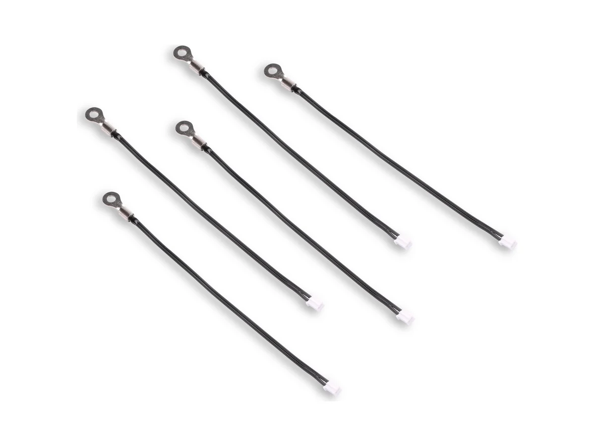
| J1 · standard ring | Ring Ø7 mm, hole Ø3.2 mm · terminal 16.5 mm · 50 mm to sleeve · cable length L | Per configuration | Sensing head 0 °C to +150 °C · approx. 6 s on hot plate | Nickel-plated brass · 15 mm sleeve · PVC cable | Surface temperature sensing. Validate bolt torque and contact, wire and dielectric strength. |
| J2 · high-temperature ring | Ring Ø7 mm, hole Ø3.2 mm · terminal 16.5 mm · cable length L | Per configuration | Sensing head −5 °C to +300 °C · approx. 6 s on hot plate | Nickel-plated brass · 100 mm sleeve · fluororesin wire | Heater and tool surface sensing. Validate the temperature limits of the full assembly, isolation and life. |
| J3 · compact ring | Ring Ø5.5 mm, hole Ø3.5 mm · terminal 12.2 mm · cable length L | Per configuration | −5 °C to +125 °C · approx. 3 s on hot plate | Nickel-plated brass · 30 mm sleeve · crosslinked-PE wire | Compact surface sensing on motors, printers and projectors. |
| H1 · floor-heating probe | ABS-shell cable probe | Per configuration | −40 °C to +120 °C · <5 s | ABS shell · cable and termination per configuration | Floor-heating control. Validate ingress, chemical resistance, cable, installation and long-term drift. |
| H2 · water probe | Single-ended glass NTC in stainless-steel housing | Per configuration | −40 °C to +150 °C · <2 s to 90% in water | Stainless-steel housing · harness and connector per configuration | Hot-water, coffee-machine and toilet water sensing. Validate pressure, immersion, materials and food-contact requirements. |
| H3 · overmolded defrost probe | Injection-molded head Ø5 × 25 mm | Per configuration | −30 °C to +120 °C · <5 s | Integrated cable overmold | Heat-pump defrost and wet-equipment sensing. Validate ingress, freeze-thaw and mounted response. |
Start with the measured medium, mechanical interface, mission profile and total temperature-error budget. Then specify one B25/50 family and R25 value, the assembly drawing, wire and connector, response method and qualification plan. The constructions shown can be configured.
Specify air, liquid, pipe, surface, battery, engine or appliance location; continuous and excursion temperature, pressure and flow, fluids, humidity and condensation, vibration, ingress, life and applicable equipment, automotive or safety standards.
Choose R25 and B25/50 from the 11 families. R/T table, ±°C band, wire-resistance compensation, self-heating, interpolation, calibration and drift data for the configuration on request.
Select a probe, ring terminal, thread, PCB, overmold or cable design. Define every dimension and tolerance, material, seal, terminal, torque or contact force, insertion depth, orientation and thermal path.
Define conductor and insulation, length and tolerance, connector, keying and pinout, crimping, welding, potting or overmolding, strain relief, finished electrical and leak test, packing and traceability.
Validate response and accuracy in the actual medium and mounting, plus thermal life and cycling, damp heat with bias, ingress, fluids, salt spray, vibration and shock, cable flex and pull, connector retention, EMC where relevant and curve drift after test.
Define curve, sensing head, dimensions, materials, wire and connector, length, mounting, packing and test plan before design-in or sourcing.
Include element R/T tolerance and drift, wire and contact resistance, ADC and reference error, self-heating, mounting gradient, response lag, interpolation and calibration.
Liquid, air, hot-plate, 63.2% time constant and 90% response are different measurements. Define the actual medium, flow or contact, temperature step, fixture and tolerance, then validate in the installed system.
Resin-to-wire, metal-to-potting, crimp, overmold, connector and threaded or ring interfaces control ingress, strain and heat transfer. Validate seal and leak tightness, pull and flex, torque, vibration, corrosion and thermal cycling together.
EV/HEV use does not prove AEC-Q200 or PPAP qualification of the assembly, and a fire-alarm sensor does not certify the alarm system. Require reports and certificate scope for the delivered configuration.