NTC-PP

PP Series NTC Inrush Current Limiters

Resistance R252.5–200 Ω
Max. steady-state current (25 °C)0.2–5.0 A
Residual resistance at max. current0.088–5.007 Ω
B value2,500–3,400 K
Disc size5D–20D
Operating temperature−40 °C to +155 °C

Phenolic-coated radial power NTC thermistors for inrush current limiting. R25 2.5–200 Ω, max. steady-state current up to 5 A, operating temperature up to +155 °C.

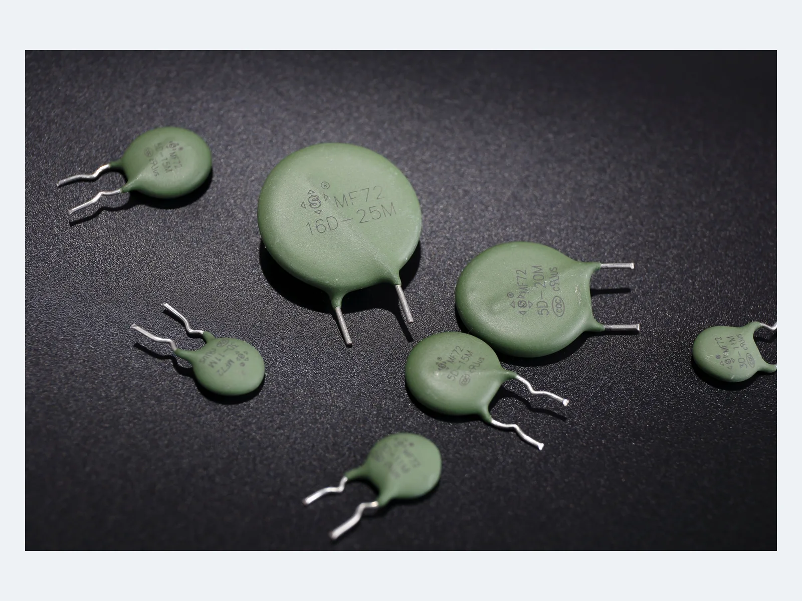
Typical appearance, power NTC thermistors

Part numbers

508

Showing 25 of 508 part numbers

MF0505001M1BN0FPB05D-555±2010.3532,5005
MF0505001M3BA0FPB05D-555±2010.3532,5005
MF0505001M3BA0FPB005D-555±2010.3532,5005
MF0505001M3BA5FPB05D-555±2010.3532,5005
MF0505001M3PX8FPB05D-555±2010.3532,5003.5
MF0505001M3TX5FPB05D-555±2010.3532,5004
MF0505001M3TX8FPB05D-555±2010.3532,5004
MF0505001M4BA0FPB05D-555±2010.3532,5005
MF0505001M4BA2FPB005D-555±2010.3532,5005
MF0505001M4BA5FPB05D-555±2010.3532,5005
MF0505001M4BA5FPB005D-555±2010.3532,5005
MF0505001M4BN0FPB05D-555±2010.3532,5005
MF0505001M4BN0FPB005D-555±2010.3532,5005
MF0505001M4BP0FPT05D-555±2010.3532,5005
MF0505001M4TA5FPB05D-555±2010.3532,5004
MF0505002M4BA5FPBD5D-555±2010.3532,5005
MF05050A5M3BX9FPBD5D-555±2010.3532,5005
MF05050A5M3TX9FPBD5D-555±2010.3532,5004
MF05050A5M8TX9FPBD5D-555±2010.3532,5004
MF05100X7M1TN0FPB010D-5510±200.70.7712,6004
MF05100X7M4BA3FPB010D-5510±200.70.7712,6005
MF05100X7M4BA5FPB0010D-5510±200.70.7712,6005
MF05100X7M4BN0FPB010D-5510±200.70.7712,6005
MF05100X7M4BN0FPB0010D-5510±200.70.7712,6005
MF05100X7M4BP0FPT010D-5510±200.70.7712,6005

— = not specified

Need a value that is not listed? Send us your specification.

Engineering details

Overview

Phenolic-coated radial power NTC thermistors (MF72 type) for inrush current limiting. Disc sizes 5D to 20D, R25 2.5–200 Ω ±20%, max. steady-state current 0.2–5.0 A at 25 °C, residual resistance 0.088–5.007 Ω. Operating temperature −40 °C to +155 °C.

Series features

  • Seven disc sizes from 5D to 20D
  • R25, max. steady-state current, residual resistance, B value, thermal time constant and dissipation constant specified per part number
  • Phenolic-resin coating; bulk or taped packing and five lead forms
  • CQC and VDE certified, UL/cUL recognized to UL 1434; coverage depends on model and construction
Specifications
FunctionSelf-heating radial NTC thermistor for inrush current limiting. High cold resistance limits the turn-on current; resistance falls as load current heats the ceramic.
TypePP (phenolic coating), MF72 power NTC thermistor type
EncapsulationPhenolic resin · code P = phenolic, RoHS; R = phenolic, halogen-free
Disc sizes5D · 7D · 9D · 11D · 13D · 15D · 20D
Rated zero-power resistance R252.5–200 Ω; available values depend on disc size
R25 toleranceM = ±20%
Max. steady-state current0.2–5.0 A at 25 °C; depends on R25 and disc size
Residual resistance at max. current0.088–5.007 Ω
B value2,500–3,400 K ±10% (reference temperatures and R/T data on request)
Thermal time constant<18 to <105 s; per part number
Dissipation constant>6 to >25 mW/°C; per part number
Operating temperature−40 °C to +155 °C
Max. voltage and capacitanceMax. operating voltage and permissible DC-bus capacitance on request. R25 and max. current alone do not qualify an inrush design.
Restart and recoveryMin. off-time, resistance-recovery curve and repetitive-start limits on request. A hot NTC gives little inrush limiting at restart.
Dimensions, 5DD max. 6.5 mm · T max. 4.0 mm · lead pitch F 5.0 ±0.5 mm · lead Ø d 0.6 ±0.05 mm
Dimensions, 7DD max. 8.0 mm · T max. 4.5 mm · lead pitch F 5.0 ±0.5 mm · lead Ø d 0.6 ±0.05 mm
Dimensions, 9DD max. 9.0 mm · T max. 5.5 mm · lead pitch F 5.0 ±0.5 mm · lead Ø d 0.6 ±0.05 mm
Dimensions, 11DD max. 11.5 mm · T max. 6.0 mm · lead pitch F 7.5 ±0.5 mm · lead Ø d 0.8 ±0.05 mm
Dimensions, 13DD max. 14.5 mm · T max. 6.5 mm · lead pitch F 7.5 ±0.5 mm · lead Ø d 0.8 ±0.05 mm
Dimensions, 15DD max. 16.5 mm · T max. 6.5 mm · lead pitch F 7.5 ±0.5 mm · lead Ø d 0.8 ±0.05 mm
Dimensions, 20DD max. 21.5 mm · T max. 7.0 mm · lead pitch F 10.0 ±0.5 mm · lead Ø d 1.0 ±0.05 mm
Lead formsLong straight · short straight · single outward bend · inward bend · front/rear raised
Lead lengthLong straight ≥16 mm; short and bent forms 2.5–<6 mm ±0.5 mm or 6–10 mm ±1.0 mm. Coating-to-bend height depends on the lead form.
Lead pitch codesB = 5.0 mm · E = 7.5 mm · D = 10.0 mm
PackingB = bulk · T = taped; taping for 5.0 and 7.5 mm lead pitch; H0 and component pitch depend on the lead form
Hand soldering and rework350 °C max. · 3 s max. · solder point at least 2 mm from the coating
Storage climate≤35 °C · ≤70% RH
Storage12 months · first in, first out · sealed with desiccant; avoid corrosive, oxidizing, flammable or explosive gases, oil, water, solvents and direct sunlight
Climate category (CQC)40/155/42
Environmental complianceRoHS and REACH compliant; encapsulation code R is halogen-free. Material declarations on request.
Further dataOn request: current derating and hot resistance versus ambient temperature; inrush energy rating (J or test capacitance at 110/120 VAC and 230/240 VAC); coating flammability class, abnormal-overload behavior and max. surface temperature; reliability test results.
System protectionA power NTC thermistor is not a fuse, relay, isolation device or hot-restart limiter. Coordinate fault current, bypass contacts, enclosure temperature, fire containment and service behavior at equipment level.
Variants

Ranges by dielectric, package and lead style within this series.

VariantBody dimensionsR25 rangeMax. steady-state current / residual resistanceLead / land patternNotes
5D-PPD max. 6.5 mm · T max. 4.0 mm5–60 Ω0.3–1.0 A · 0.353–2.653 ΩF 5.0 ±0.5 mm · d 0.6 ±0.05 mmSmallest size.
7D-PPD max. 8.0 mm · T max. 4.5 mm5–50 Ω0.2–2.0 A · 0.283–3.7059 ΩF 5.0 ±0.5 mm · d 0.6 ±0.05 mmCompact size for power inputs.
9D-PPD max. 9.0 mm · T max. 5.5 mm3–200 Ω0.5–3.0 A · 0.120–5.007 ΩF 5.0 ±0.5 mm · d 0.6 ±0.05 mmWidest R25 range, up to 200 Ω.
11D-PPD max. 11.5 mm · T max. 6.0 mm2.5–120 Ω1.1–4.0 A · 0.095–2.253 ΩF 7.5 ±0.5 mm · d 0.8 ±0.05 mmMid-size disc. Validate thermal derating and life at the actual load.
13D-PPD max. 14.5 mm · T max. 6.5 mm2.5–120 Ω1.2–5.0 A · 0.088–2.124 ΩF 7.5 ±0.5 mm · d 0.8 ±0.05 mmHigher current, up to 5.0 A.
15D-PPD max. 16.5 mm · T max. 6.5 mm4–120 Ω1.8–5.0 A · 0.112–1.652 ΩF 7.5 ±0.5 mm · d 0.8 ±0.05 mmLarge size. Validate energy and hot loss before design-in.
20D-PPD max. 21.5 mm · T max. 7.0 mm6–16 Ω4.0–5.0 A · 0.113–0.212 ΩF 10.0 ±0.5 mm · d 1.0 ±0.05 mmLargest size in the series. Availability on request.
Selection guide

Start from the energy and the permissible inrush current of the input stage, not from disc size. Then select R25, check continuous current and hot loss at max. ambient temperature, define the restart duty, and specify approval, drawing and packing with the part number.

  1. Calculate startup energy and duty

    Define line or DC-bus voltage, tolerance, frequency, downstream capacitance or transformer magnetizing energy, series impedance, number of starts and min. off-time. The energy (J) or test-capacitance rating, available on request, must exceed the application stress.

  2. Select cold resistance from the permissible inrush

    Estimate R25 from peak voltage, existing series impedance and the weakest bridge, fuse, switch or load limit. Include the ±20% R25 tolerance and the coldest start temperature.

  3. Check current, hot resistance and temperature

    Max. current and residual resistance apply only at their stated condition (25 °C). Data on request for ambient derating, hot resistance versus current, body and lead temperature, airflow and mounting conditions, and life at the actual load.

  4. Define restart, bypass and fault behavior

    A hot NTC has low resistance and limits little at restart. Define recovery time, repetitive starts, bypass-relay timing and contact stress, fuse coordination, abnormal overload and safe end of life.

  5. Specify the exact part number

    Fix R25, max. current, drawing, lead form, packing, coating code and approval scope with the exact part number before production approval.

Approvals & reliability

Approvals & qualifications

Approvals are issued for MF72 types. CQC approval covers climate category 40/155/42.

AgencyStandardCertificateScope
CQC certification markCQCGB/T 6663.1-2007 · CQC11-471552-2015 ruleCQC19001213204MF72 types, ±20%, disc sizes 5, 7, 9, 11, 13, 15 and 20 mm, listed per resistance value; climate category 40/155/42. Valid to 9 Apr 2029, subject to surveillance.
UL certification markUL / cULUL 1434E474052Recognized component. The file lists individual inrush-limiting NTC models with their conditions of acceptability.
VDE certification markVDEDIN EN 60539-1:2017-01 · EN 60539-1:201640050168Covers listed MF72 types under factory surveillance.

Each certificate covers the types and ratings listed on it.

Design notes

Start from energy, not only R25

For a capacitor-input supply, ½CV² is a first estimate; source impedance and waveform also matter. The selected part needs an energy or test-capacitance rating, available on request, above the actual startup energy and duty.

Protect the weakest series element

Choose cold resistance from peak voltage, minimum source impedance, tolerance and cold temperature so that the bridge, fuse, switch, relay contacts and load stay below their turn-on limits.

Treat max. current as a thermal rating

Continuous current heats the NTC. Validate ambient, airflow, PCB heat sinking, enclosure temperature, residual resistance, loss, body and lead temperature and current derating. The 25 °C value does not apply at higher ambient temperature.

Do not connect NTC limiters in parallel

Self-heating causes current hogging between parallel parts. If one part cannot meet the current or energy requirement, select a larger size or an active precharge or bypass circuit.

Design for hot restart and bypass timing

A recently energized NTC stays hot and low in resistance and may not limit a fast restart. Define min. off-time, recovery detection, bypass-relay timing, contact stress and repetitive-start fault behavior.

Control hot surfaces, fusing and assembly

Keep spacing from heat-sensitive materials, coordinate upstream protection and fire containment, use the lead and packing drawing of the exact part number, observe the 350 °C / 3 s rework limit and store the parts dry and sealed.

Part numbering

Example ordering code. Not every combination is available.

MF · 05 · 100 · X8 · M · 3 · B · X7 · F · P · B · 0 · 0

CodeMeaning
MFPower NTC thermistor prefix (MF72 type)
05Disc diameter: 05 = 5 mm; up to 20 mm
100R25: 100 = 10 Ω; decimal values written as 0R5
X8Max. steady-state current: X8 = 0.8 A; other codes on request
MR25 tolerance: M = ±20%
3Lead form: 3 = short straight; 1 = long straight, 2 = single outward bend, 4 = inward bend, 8 = front/rear raised
BLead pitch: B = 5.0 mm; E = 7.5 mm, D = 10.0 mm
X7Lead length, bulk: X0–X9 cover 2.0–2.9 mm; exact length: see part drawing
FLead material: F = tin-plated copper-clad steel wire
PEncapsulation: P = phenolic resin, RoHS; R = phenolic resin, halogen-free
BPacking: B = bulk; T = taped
0Factory code, assigned by STE