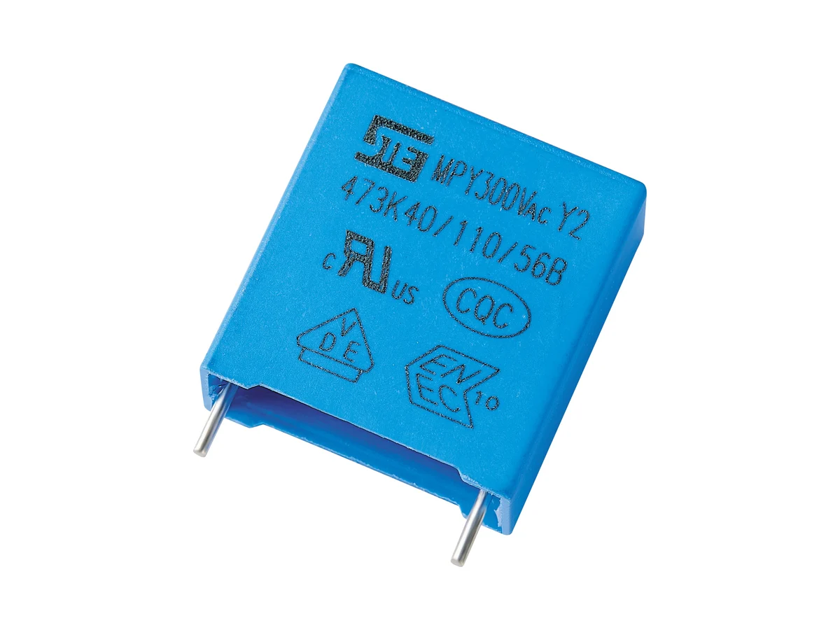
| Safety function | Class Y2 · line-to-earth / line-bypass EMI suppression · basic or supplementary insulation; not for reinforced-insulation (Y1) positions |
|---|
| Construction | Metallized polypropylene film · boxed, resin-encapsulated |
|---|
| Reference standards | IEC / EN / UL 60384-14 · approvals to IEC 60384-14:2013 + AMD1:2016 |
|---|
| Rated AC voltage UR | 250 · 275 · 300 · 350 VAC |
|---|
| Capacitance range | 0.001–1.2 µF · available values depend on rated voltage, body size, tolerance and approval scope |
|---|
| Capacitance tolerance | ±10% (K) · ±20% (M, on request) |
|---|
| Leakage current | Calculate the mains-frequency current from capacitance including tolerance, voltage and frequency; check it against the equipment leakage limit |
|---|
| Operating temperature | −40 °C to +110 °C |
|---|
| Climatic category / flammability | 40/110/56 · passive flammability category B |
|---|
| DC voltage rating (STE-specified) | 1,500 VDC at 85 °C · 1,000 VDC at 105 °C · derating and lifetime data on request |
|---|
| DC approval | VDE certificate 40056386 includes no Annex H (DC) approval; the DC rating is not a certified safety-capacitor DC approval |
|---|
| Dissipation factor | tan δ ≤0.15% |
|---|
| Insulation resistance, CR ≤0.33 µF | ≥15,000 MΩ at 20 °C, 100 VDC, 60 s |
|---|
| Insulation resistance, CR >0.33 µF | Time constant ≥5,000 s (T = IR [MΩ] × CN [µF]) at 20 °C, 100 VDC, 60 s |
|---|
| Voltage proof, terminal to terminal | 1,500 VAC, 1 s, or 3,500 VDC, 5 s |
|---|
| Voltage proof, terminals to case | 2 × UR + 1,500 VAC, min. 2,000 VAC |
|---|
| Impulse test voltage | On request, including the test circuit |
|---|
| Impulse sequence | 24 pulses · 9 s charge / 2 s discharge cycle |
|---|
| Self-ignition test | U = UR · U1 = 5.0 kV · 20 discharges of the energy-storage capacitor per sample · 5 s interval |
|---|
| Humidity robustness | No biased 85/85 humidity test; the VDE approval includes no IEC 60384-14 Annex I humidity grade. For humid environments, see MPY/Y2-THB. |
|---|
| Body dimensions | W 10–41.5 · H 11–41 · T 5–27.5 mm, depending on rated voltage and capacitance |
|---|
| Lead pitch | 7.5 · 10 · 15 · 22.5 · 27.5 · 37.5 mm |
|---|
| Pitch codes | N 10 · Q 15 · T 22.5 · V 27.5 mm · codes for 7.5 and 37.5 mm on request |
|---|
| Lead diameter | 0.6 mm (pitch 7.5–10 mm) · 0.8 mm (15–27.5 mm) · 1.0 mm (37.5 mm) |
|---|
| Lead and packing forms | Long straight · inner-bent · straight, taped · bent, taped |
|---|
| Taped lead spacing F | 7.5 / 10 / 15 / 20–22.5 mm; F = 5 mm is not offered in this series |
|---|
| Soldering profile, PP | Preheat ≤110 °C · soldering ≤120 °C · ≤15 s |
|---|
| Soldering profile, PE | Preheat ≤125 °C · soldering ≤160 °C · ≤15 s |
|---|
| Soldering profile selection | PP or PE, depending on the part number; on request |
|---|
| Hand soldering / rework | Iron ≤350 °C · ≤3 s · ≥2 mm from the coating |
|---|
| Reflow soldering | Not permitted; film shrinkage can degrade performance |
|---|
| Storage | In unopened package: ≤35 °C, ≤70% RH, ≤12 months. Keep away from corrosive gases to preserve lead solderability. |
|---|
| Environmental compliance | RoHS and REACH compliant · code E = RoHS, F = RoHS + halogen-free |
|---|
| Further data | On request: tan δ measurement conditions · voltage-proof test duration, terminals to case · leakage and failure-current behavior · dry-heat life · dV/dt · current · ESR · thermal · humidity · vibration · lead strength |
|---|