MPY/Y2-THB

MPY/Y2-THB Series Metallized Polypropylene Film Interference Suppression Capacitors (Class Y2, THB)

Safety classY2, line-to-earth
THB test85 °C / 85% RH · 240 VAC · 500 h
Rated voltage250 / 275 / 300 / 350 VAC
Capacitance0.001–1.2 µF
Tolerance±10% / ±20%
Operating temperature−40 °C to +110 °C
CQC certification markVDE certification markENEC certification markIECEE CB scheme markUL certification mark

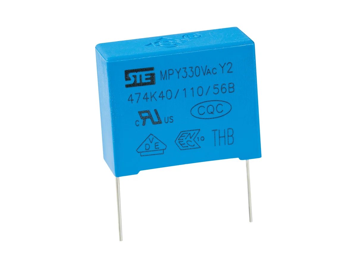
Boxed metallized polypropylene film capacitors for line-to-earth EMI suppression in humid environments, Class Y2. Rated 250–350 VAC, 1 nF–1.2 µF.

Series product photograph

Part numbers

8

Showing 8 of 8 part numbers

Y2Q1102KN135130090040EV80.001±10300Y2
Y2Q1102KN1A5130090040EV80.001±10300Y2
Y2Q1472KN135130110050EV80.0047±10300Y2
Y2Q1472KN1A5130110050EV80.0047±10300Y2
Y2Q1103KN135130130070EV80.01±10300Y2
Y2Q1103KN1A5130130070EV80.01±10300Y2
Y2Q1223KQ135180120060EV80.022±10300Y2
Y2Q1223KQ1A5180120060EV80.022±10300Y2

— = not specified

Need a value that is not listed? Send us your specification.

Engineering details

Overview

Boxed metallized polypropylene film capacitors for line-to-earth (L/N–PE) EMI suppression in humid environments, Class Y2 to IEC / EN / UL 60384-14, for basic or supplementary insulation. Rated 250, 275, 300 and 350 VAC; 1 nF–1.2 µF; tolerance ±10% or ±20%. Biased humidity test: 85 °C / 85% RH, 240 VAC, 500 h. Operating temperature −40 °C to +110 °C.

Series features

  • Class Y2 to IEC / EN / UL 60384-14 for line-to-earth and bypass interference suppression
  • Four AC ratings: 250, 275, 300 and 350 VAC; certified range 1 nF–1.2 µF
  • THB test: 500 h at 85 °C / 85% RH and 240 VAC
  • Boxed, resin-encapsulated metallized polypropylene construction; flame-retardant to UL 94 V-0
Specifications
Safety functionClass Y2 · line-to-earth / line-bypass EMI suppression · basic or supplementary insulation; not for reinforced-insulation (Y1) positions
ConstructionMetallized polypropylene film · boxed, resin-encapsulated
Reference standardsIEC / EN / UL 60384-14 · GB/T 6346.14-2023
Rated AC voltage UR250 · 275 · 300 · 350 VAC
Capacitance range0.001–1.2 µF · available values depend on rated voltage, body size and approval scope
Capacitance tolerance±10% (K) · ±20% (M)
Leakage currentCalculate the mains-frequency current from capacitance including tolerance, voltage and frequency; check it against the equipment leakage limit
Operating temperature−40 °C to +110 °C
Climatic category / flammability40/110/56 · passive flammability category B
Dissipation factortan δ ≤0.15%
Insulation resistance, CR ≤0.33 µF≥15,000 MΩ at 20 °C, 100 VDC, 60 s
Insulation resistance, CR >0.33 µFTime constant ≥5,000 s (T = IR [MΩ] × CN [µF]) at 20 °C, 100 VDC, 60 s
Voltage proof, terminal to terminal1,500 VAC, 1 s, or 3,500 VDC, 5 s
Voltage proof, terminals to case2 × UR + 1,500 VAC, min. 2,000 VAC
Impulse sequence24 pulses · 9 s charge / 2 s discharge cycle
Self-ignition testU = UR · U1 = 5.0 kV · 20 discharges of the energy-storage capacitor per sample · 5 s interval
Biased humidity test (THB)85 ±2 °C · 85 ±2% RH · 240 VAC · 500 h
THB acceptance|ΔC/C| ≤10%; other post-test limits on request
IEC 60384-14 Annex I gradeNone: VDE certificate 40056386 includes no Annex I humidity-robustness grade. The 500 h THB test is an STE test, not a certified grade.
DC operationNo continuous DC rating; the VDE approval includes no Annex H (DC) approval
Body dimensionsW 10–41.5 · H 9–41 · T 4–27.5 mm, depending on rated voltage and capacitance
Lead pitch7.5 · 10 · 15 · 22.5 · 27.5 · 37.5 mm
Pitch codesN 10 · Q 15 · T 22.5 · V 27.5 mm · 7.5 and 37.5 mm codes on request
Lead diameter0.6 mm (pitch 7.5–10 mm) · 0.8 mm (15–27.5 mm) · 1.0 mm (37.5 mm)
Lead and packing formsLong straight · inner-bent · straight, taped · bent, taped
Hand soldering / reworkIron ≤350 °C · ≤3 s · ≥2 mm from the coating
Reflow solderingNot permitted; film shrinkage can degrade performance
StorageIn unopened package: ≤35 °C, ≤70% RH, ≤12 months. Keep away from corrosive gases to preserve lead solderability.
Further dataOn request: impulse test voltage and test circuit; tan δ measurement conditions; voltage-proof duration, terminals to case; ESR, impedance, RMS current, self-heating and frequency derating; leakage and failure-current behavior, dry-heat life, dV/dt, current, thermal and mechanical qualification data
Variants

Ranges by dielectric, package and lead style within this series.

VariantBody dimensionsRated voltage / capacitanceConstruction / classLead / land patternNotes
7.5 mmW 10 · H 9–15 · T 4–8 mm250–350 VAC · 0.001–0.0039 µFMetallized PP · Y2 · K/MP 7.5 ±0.5 · d 0.6 ±0.05 mmSmallest body.
N · 10 mmW 13 · H 9–15 · T 4–7 mm250–350 VAC · 0.001–0.01 µFMetallized PP · Y2 · K/MP 10 ±0.5 · d 0.6 ±0.05 mm—
Q · 15 mmW 18 · H 12–21 · T 6–12 mm250–350 VAC · 0.01–0.047 µFMetallized PP · Y2 · K/MP 15 ±0.5 · d 0.8 ±0.05 mmIncludes larger cases for higher rated voltages.
T · 22.5 mmW 26 · H 17–23 · T 8.5–13 mm250–350 VAC · 0.047–0.1 µFMetallized PP · Y2 · K/MP 22.5 ±0.5 · d 0.8 ±0.05 mmMid-capacitance range. Availability on request.
V · 27.5 mmW 31–31.5 · H 20–30.5 · T 11–22 mm250–350 VAC · 0.1–0.33 µFMetallized PP · Y2 · K/MP 27.5 ±0.5 · d 0.8 ±0.05 mmLeakage current rises with capacitance; check it against the equipment limit.
37.5 mmW 41.5 · H 28–41 · T 14–27.5 mm250–350 VAC · 0.39–1.2 µFMetallized PP · Y2 · K/MP 37.5 ±0.5 · d 1.0 ±0.05 mmHigh capacitance values may exceed tight equipment leakage limits.
Selection guide

Start with the insulation position: Class Y2 is a line-bypass class for basic or supplementary insulation where the equipment standard permits it. It does not replace Y1 in reinforced-insulation positions. Then define leakage current, AC voltage, capacitance, impulse and humidity requirements and dimensions.

  1. Confirm that Y2 is permitted

    Use Y2 from line to protective earth or in a bypass position only when the insulation architecture and equipment standard permit basic or supplementary insulation. Use Y1 where reinforced insulation or the higher impulse class is required.

  2. Calculate leakage current first

    Use the capacitance including tolerance, the mains voltage and frequency to calculate line-frequency current. Include all Y capacitors and other leakage paths in the equipment limit.

  3. Select voltage and check impulse data

    Choose 250–350 VAC for the approved construction. The impulse test voltage, circuit, waveform and source impedance are available on request.

  4. Match the THB test to the mission profile

    The THB test is 500 h at 85 °C / 85% RH and 240 VAC, with a capacitance-change limit only. Certificate 40056386 grants no Annex I grade. Post-test tan δ, IR and voltage-proof data and field-life correlation are available on request.

  5. Specify geometry and process

    Specify W/H/T, pitch, lead diameter and form and packing for each capacitance and voltage. Check PCB creepage and clearance, and do not reflow-solder.

Approvals & reliability

Approvals & qualifications

CQC, VDE/ENEC, IECEE CB and UL/cUL approvals cover MPY Y2 from 1 nF to 1.2 µF at 250–350 VAC. VDE certificate 40056386 includes neither an Annex H (DC) approval nor an Annex I humidity grade.

AgencyStandardCertificateScope
CQC certification markCQCGB/T 6346.14-2023 + AMD1:2016CQC23001379254MPY Y2, 0.001–1.2 µF, 250/275/300/350 VAC, ±10% (K) or ±20% (M), passive flammability category B, 40/110/56. Issued 10 Mar 2023.
VDE certification markENEC certification markVDE / ENECEN 60384-1440056386MPY Y2, 0.001–1.2 µF, 250/275/300/350 VAC, K/M, climatic category 40/110/56, passive flammability category B. No Annex H (DC) approval; no Annex I humidity grade.
IECEE CB scheme markIECEE CBIEC 60384-14DE1-67208MPY Y2, 1 nF–1.2 µF, K/M, 250/275/300/350 VAC, 40/110/56/B. Test report 300758-TL3-1.
UL certification markUL / cULUL 60384-14E208107MPY Y2, 0.001–1.2 µF, 250/275/300/350 VAC, −40 to +110 °C, tolerance K/M. No humidity grade.

Each certificate covers the types and ratings listed on it.

Reliability tests

Voltage proof, an impulse test sequence, a self-ignition test and a biased damp-heat test (500 h) are specified.

TestConditionAcceptance
Impulse test24 pulses · 9 s charge / 2 s dischargeTest voltage, circuit and post-test limits on request
Self-ignition testU = UR · U1 = 5.0 kV · 20 discharges per sample · 5 s intervalTest energy and pass criteria on request
Biased damp heat (THB)85 ±2 °C · 85 ±2% RH · 240 VAC · 500 h|ΔC/C| ≤10%; post-test tan δ, IR, voltage-proof, visual and sample-size criteria on request
Design notes

Y2 does not provide reinforced insulation

Use Y2 for line-to-earth EMI suppression where basic or supplementary insulation is allowed. Reinforced primary-to-secondary barriers and higher impulse requirements need a Y1 capacitor with the corresponding approval.

Leakage current sets the usable capacitance

Higher Y capacitance improves common-mode attenuation but raises mains-frequency current. Sum every Y capacitor and leakage path at maximum voltage, frequency and tolerance, and compare the total with the equipment standard.

Voltage rating is part-specific

The approvals include 350 VAC; availability by voltage rating on request. Use the marking, body size and certificate scope of the ordered part number.

THB test is not a certified humidity grade

The THB test is 500 h at 85 °C / 85% RH and 240 VAC; the VDE approval includes no Annex I grade. Lifetime in humid service needs the full test report, post-test electrical limits and mission-profile correlation.

Spacing, assembly and failure path

Define PCB creepage and clearance, lead form, soldering, cleaning and coating; do not reflow-solder. Coordinate protective-earth integrity, fusing and open- and short-circuit failure analysis with the equipment standard.

Part numbering

Example ordering code. Not every combination is available.

Y2 · Q1 · 103 · K · Q · 1 · B0 · 180 · 120 · 060 · E · V · 8

CodeMeaning
Y2Safety class Y2 and series
Q1Rated voltage: Q1 = 300 VAC; E2 = 250, P2 = 275, R2 = 350 VAC
103Capacitance code: 103 = 10 nF
KCapacitance tolerance: K = ±10%; M = ±20%
QLead pitch: Q = 15 mm; N = 10, T = 22.5, V = 27.5 mm. 7.5 and 37.5 mm codes on request.
1Lead form: 1 = long straight; 2 = inner-bent, 5 = straight taped, 6 = bent taped
B0Lead length: B0 = 20.0 mm
180Body width: 180 = 18.0 mm
120Body height: 120 = 12.0 mm
060Body thickness: 060 = 6.0 mm
EEnvironmental: E = RoHS; F = RoHS + halogen-free
VCase color: V = blue; E = gray
8STE internal management code