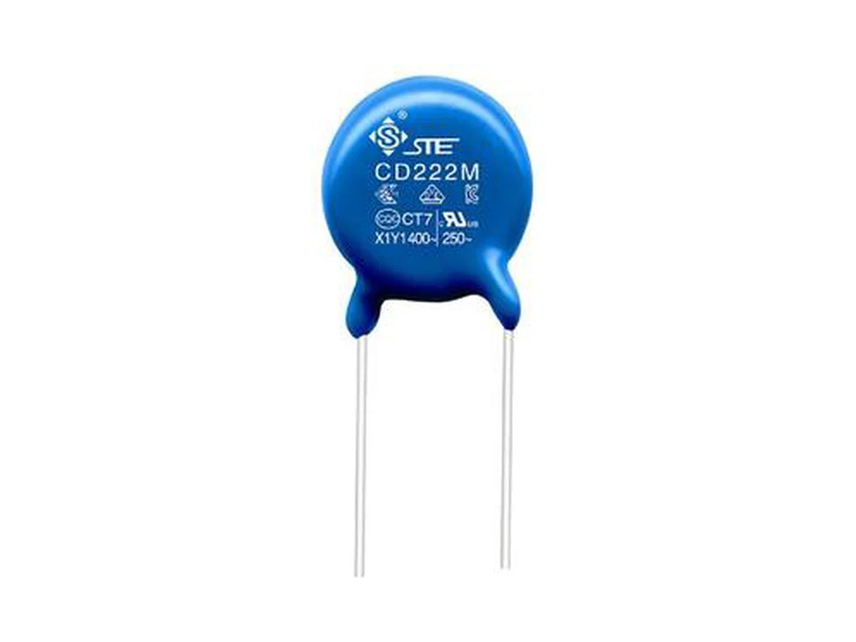
| Function | Radial single-layer ceramic safety capacitor for X1/Y1 EMI suppression and isolation coupling. The capacitor alone is not a complete reinforced-insulation system or equipment approval. |
|---|
| Safety class | IEC 60384-14 · X1 760 VAC / Y1 500 VAC |
|---|
| Reinforced insulation | Y1 supports reinforced-insulation positions only when creepage, clearance, pollution degree, overvoltage and abnormal-condition design of the equipment also comply |
|---|
| Automotive qualification | AEC-Q200 qualified part numbers available; AEC-Q200 revision, qualification report and qualified part-number list on request |
|---|
| Damp heat | 85 °C / 85% RH, 1,000 h |
|---|
| Annex I humidity grade | Not assigned in VDE approval 40056133; the 85/85 test is not an Annex I grade IIIB rating |
|---|
| Temperature cycling | 1,000 cycles, −55 °C to +125 °C |
|---|
| Climatic category | 40/125/21 (CQC, VDE) |
|---|
| Operating temperature | −40 °C to +125 °C (approval range); operating grade and voltage derating on request |
|---|
| Capacitance range | Y5P 100–2,200 pF (12 values) · Y5U 330–4,700 pF (12 values) |
|---|
| Capacitance tolerance | Y5P K ±10% · Y5U K ±10% up to 820 pF, M ±20% from 1,000–4,700 pF |
|---|
| Body dimensions, Y5P | D max. 7.5–18.0 · T max. 5.0–6.5 mm, depending on value |
|---|
| Body dimensions, Y5U | D max. 7.5–17.0 · T max. 6.0–6.5 mm, depending on value |
|---|
| Leads | F 10.0 ±0.5 mm · d 0.60 or 0.65 ±0.05 mm, depending on part |
|---|
| Measuring conditions | Capacitance and dissipation factor at 25 °C · 1 kHz · 1 Vrms |
|---|
| Dissipation factor | ≤2.5% (initial) |
|---|
| Insulation resistance | ≥10,000 MΩ |
|---|
| Dielectric strength | 4,000 VAC |
|---|
| DC rating | Rated for X1/Y1 AC. VDE Annex H covers 1,500 VDC for Y5U/Y5V only; DC rating of individual part numbers on request |
|---|
| Leakage current | No component limit specified; calculate from maximum C, f and V and check the touch-current budget of the equipment |
|---|
| Lead forms and coating extension | Long straight · short straight · single outer-bent · front/rear raised; coating extension ≤2.5 mm (body ≤10 mm) or ≤3.0 mm (body >10 mm) where applicable |
|---|
| Bulk lead length | Long straight ≥16.0 mm · short/bent 2.5–<6.0 mm ±0.5 or 6.0–10.0 mm ±1.0 |
|---|
| Taping | F 10 mm; P0 12.7 / P 25.4 mm or P0 15 / P 15 mm; 18 mm carrier tape; seating height depends on lead form |
|---|
| Wave soldering | Preheat 30–130 s to 115 °C · rapid rise to 260 °C max. · solder ≤10 s · cooling ≤5 °C/s; validate immersion depth and board thermal mass |
|---|
| Hand rework | 360 °C max. · 3 s max. · solder joint ≥2 mm from coating |
|---|
| Further data on request | Damp-heat bias voltage, sample size, recovery and post-test limits · temperature-cycling dwell, transfer time and post-test limits · insulation-resistance measuring voltage and charging time · dielectric-strength frequency, duration and ramp · Y1 impulse voltage, 1.2/50 µs waveform, polarity and number of pulses · capacitance versus temperature, AC/DC bias, frequency and aging for Y5P, Y5U and Y5V · reflow suitability, cleaning and coating compatibility, lead-forming limits, storage conditions and shelf life · endurance, biased humidity, vibration, mechanical shock, lead strength and solder-heat test results |
|---|