
STE Expands Surface Mount NTC Options for Compact Fast Chargers
Original report
STE edition
A July 2025 report highlights STE’s three SMD NTC outlines; this adaptation clarifies package-specific ratings and the limits of surge claims.
Chongdiantou reported on July 8, 2025 that STE's surface mount NTC range offered 1815, 2522 and 3225 outlines for compact power electronics. The coverage emphasized low-profile assembly, tape-and-reel packaging and applications such as fast chargers, industrial control and communications equipment.
The original headline also referred to resistance to lightning-related stress. This adaptation retains that announcement context without presenting the devices as universally lightning-proof: the report does not provide a complete surge waveform, energy limit or equipment-level qualification result.
Three outlines with different electrical limits
The report described inward lead forms and molding material meeting UL94 V-0. Its package comparison showed nominal length and width of 4.5 × 3.9 mm for 1815, approximately 6.0 × 5.6 mm for 2522, and 8.1 × 6.0 mm for 3225.
The table below distinguishes the historical report from values checked in the available formal specifications:
| Family | Cold resistance range | Temperature range | Source and scope |
|---|---|---|---|
| 1815 | 5–200 Ω | −40 to +155°C | July 2025 report; formal specification not verified |
| 2522 | 2.5–200 Ω at 25°C | −40 to +175°C | STE specification, revision 2025-03-21, page 5 |
| 3225 | 1.5–200 Ω at 25°C | −40 to +175°C | STE specification, revision 2024-01-17, page 5 |
The original report gave a 1.5 Ω lower limit for 2522. The reviewed formal table starts at 2.5 Ω, so this adaptation uses that documented boundary. Its mechanical drawing specifies 6.0 ±0.1 × 5.55 ±0.1 × 2.38 ±0.1 mm. For 3225, the documented body is 8.1 ±0.3 × 6.0 ±0.3 × 2.5 ±0.3 mm.
The report listed a thermal dissipation coefficient above 6 mW/°C for 1815. The formal 2522 table lists above 11 mW/°C. Such thermal values need their specified measurement conditions; they are not a direct measure of inrush performance on every PCB.
Current capability follows the selected resistance
The formal tables illustrate why package and resistance must be selected together. At 5 Ω, the 2522 table gives a maximum steady current of 3 A at 25°C; the 3225 table gives 4 A at 25°C. Both require temperature derating rather than carrying those current values unchanged to their upper temperature limits.
An NTC can limit startup current because its initially higher resistance changes as it heats. That operating role is distinct from clamping an external overvoltage. Any claim about surviving a lightning-related surge therefore needs defined test conditions for both the selected component and the surrounding protection circuit.
Reels for surface mount production
Chongdiantou reported 13-inch reels holding 3000 pieces for both 1815 and 2522, and 15-inch reels holding 4000 pieces for 3225. The formal 2522 and 3225 packaging pages confirm their respective reel quantities and nominal reel sizes.
These packages give designers an option for automated placement when reducing component height or consolidating assembly processes. The inward lead geometry still needs its own land pattern. Claims of stronger mounting, lower scrap or improved reliability should be evaluated on the actual board and production line rather than assumed from the SMD format.
The original report also announced a September 12 appearance at the 2025 Autumn Asia Charging Expo, at booths A35 and A36. That was a historical event notice, not a current invitation.
For product evaluation, STE's documented 2522 and 3225 families provide a starting point. The 1815 information remains announcement-level material until a formal specification is available.
Source and technical references
Original Chinese report: 松田推出扛雷贴片NTC,助力快充开发更小、更薄, Chongdiantou, 凌, July 8, 2025. 松田推出扛雷贴片NTC,助力快充开发更小、更薄
STE 2522 specification, revision 2025-03-21, and STE 3225 specification, footer revision 2024-01-17, pages 4–5 and 7–8. STE 2522 specification STE 3225 specification
English adaptation prepared for STE under authorized republication and adaptation.
Figures and tables from the original report
The following figures retain their original captions, markings and historical context. Transcribed tables present the values shown in the published images; product selection should use the specifications for the selected part.
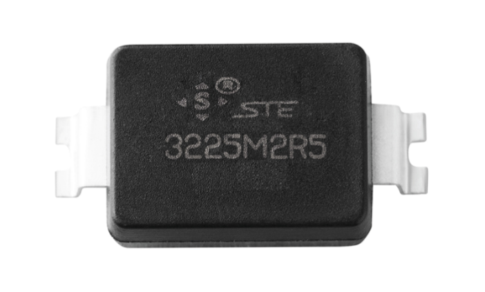
| Field | Source description |
|---|---|
| Mounting type | SMD |
| Component type | NTC: negative-temperature-coefficient thermistor |
| Approximate body dimensions | 3225≈8.1×6.0 mm;2522≈6.0×5.6 mm;1815≈4.5×3.9 mm |
| Terminal form | N: inward |
| Zero-power resistance codes | 1R5:1.5 Ω;100:10 Ω;101:100 Ω |
| Maximum steady-state current codes | 01:1 A;S5:1.5 A;02:2 A;03:3 A;04:4 A;05:5 A |
| Zero-power resistance tolerance | L: ±15%; M: ±20% |
Approximate dimensions do not replace the detailed dimensional tables.
| Item | Value / expression |
|---|---|
| Ambient temperature Ta | 60°C |
| Illustrative upper temperature Tu | 200°C |
| Source formula | ITa = [1 − (Ta − 25)/(Tu − 25)] × Imax = 80% Imax |
200°C is an illustrative calculation input, not a rated operating temperature for these parts. The accompanying tables specify upper limits of 155°C or 175°C. The source curve is not used to infer additional ratings.
| Item | Source statement |
|---|---|
| Source feature 1 | Molded package; the source states that the encapsulation material meets UL94-V0. |
| Source feature 2 | Compact package intended to save board space. |
| Source feature 3 | The source describes resistance to high temperature and humidity. |
| Source feature 4 | The source describes inrush-current limiting capability. |
| Source feature 5 | Reel packaging for automated assembly using lead-free reflow or wave soldering. |
| Applications listed by the source | Circuit protection, industrial equipment, communications equipment, consumer electronics and automotive electronics. |
These are statements in the historical source image, not independent verification of certification, environmental testing or automotive qualification. Check the specific device soldering profile before assembly.
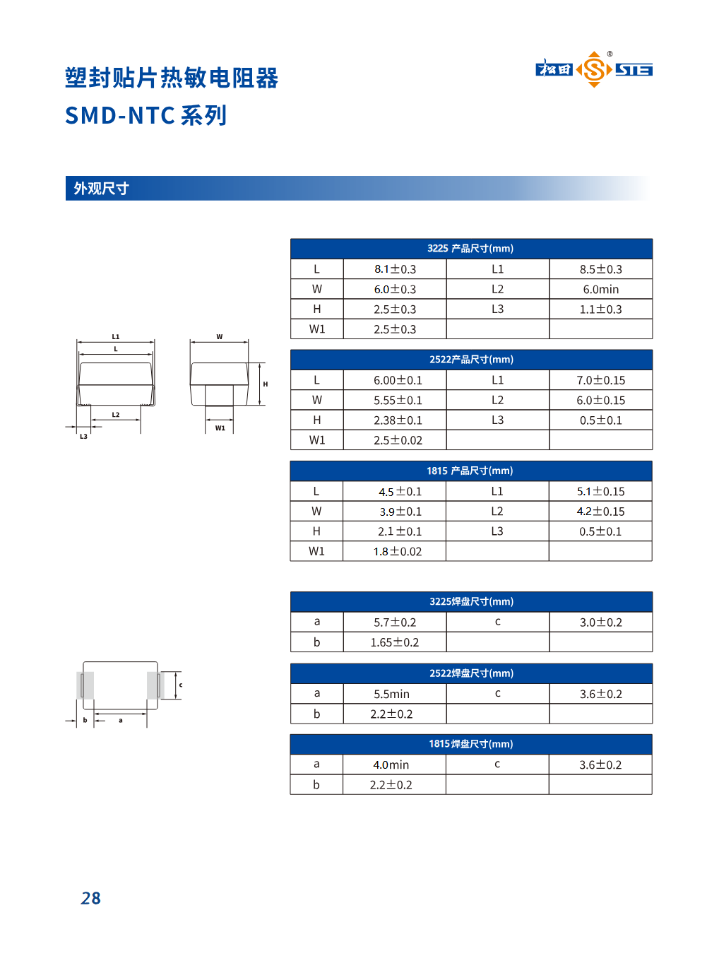
| Symbol | Dimension (mm) |
|---|---|
| L | 8.1±0.3 |
| W | 6.0±0.3 |
| H | 2.5±0.3 |
| W1 | 2.5±0.3 |
| L1 | 8.5±0.3 |
| L2 | 6.0 min |
| L3 | 1.1±0.3 |
Dimensions transcribed from the source image; see the original drawing for symbol locations.
| Symbol | Dimension (mm) |
|---|---|
| a | 5.7±0.2 |
| b | 1.65±0.2 |
| c | 3.0±0.2 |
Dimensions transcribed from the source image; see the original drawing for symbol locations.
| Symbol | Dimension (mm) |
|---|---|
| L | 6.00±0.1 |
| W | 5.55±0.1 |
| H | 2.38±0.1 |
| W1 | 2.5±0.02 |
| L1 | 7.0±0.15 |
| L2 | 6.0±0.15 |
| L3 | 0.5±0.1 |
Dimensions transcribed from the source image; see the original drawing for symbol locations.
| Symbol | Dimension (mm) |
|---|---|
| a | 5.5 min |
| b | 2.2±0.2 |
| c | 3.6±0.2 |
Dimensions transcribed from the source image; see the original drawing for symbol locations.
| Symbol | Dimension (mm) |
|---|---|
| L | 4.5±0.1 |
| W | 3.9±0.1 |
| H | 2.1±0.1 |
| W1 | 1.8±0.02 |
| L1 | 5.1±0.15 |
| L2 | 4.2±0.15 |
| L3 | 0.5±0.1 |
Dimensions transcribed from the source image; see the original drawing for symbol locations.
| Symbol | Dimension (mm) |
|---|---|
| a | 4.0 min |
| b | 2.2±0.2 |
| c | 3.6±0.2 |
Dimensions transcribed from the source image; see the original drawing for symbol locations.
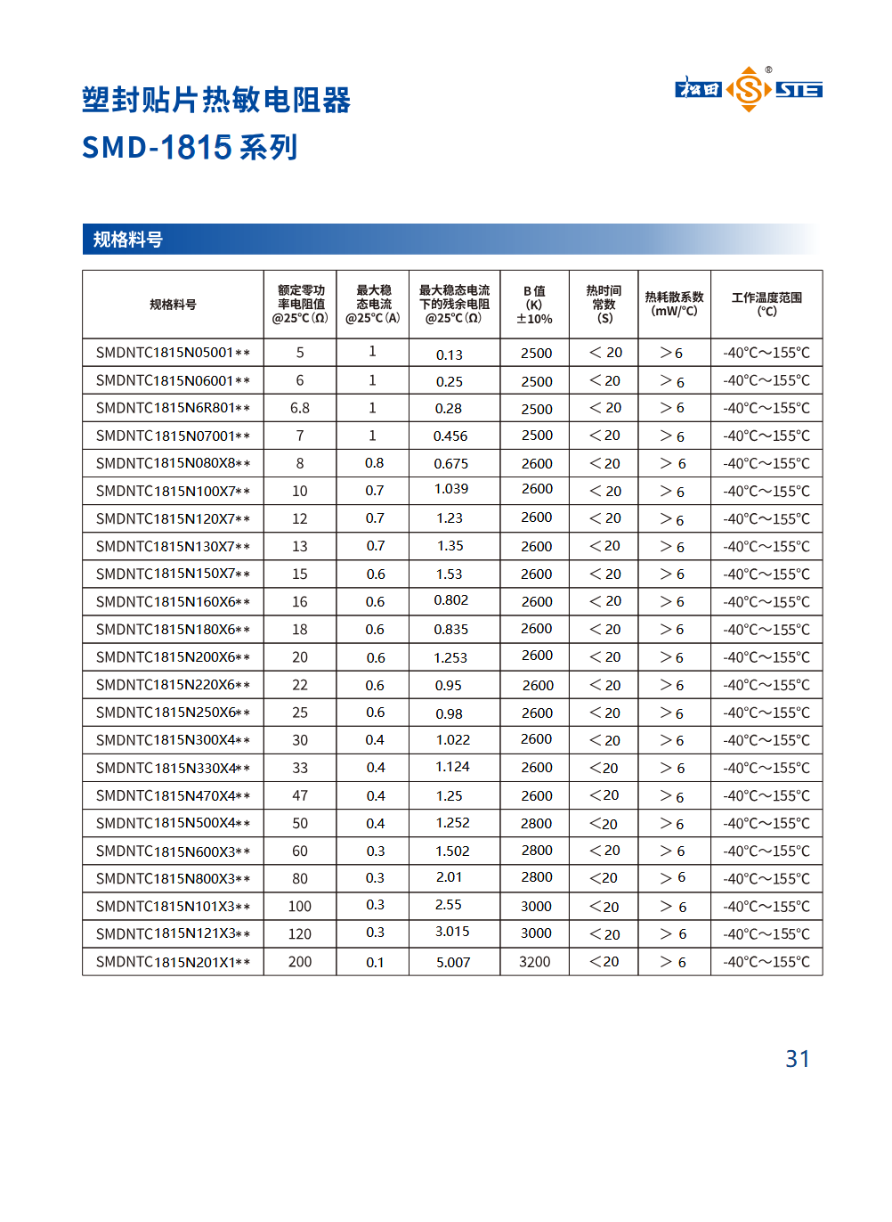
| Part number | Rated zero-power resistance at 25°C (Ω) | Maximum steady-state current at 25°C (A) | Residual resistance at maximum steady-state current, 25°C (Ω) | B value (K), ±10% | Thermal time constant (s) | Thermal dissipation factor (mW/°C) | Operating temperature (°C) |
|---|---|---|---|---|---|---|---|
| SMDNTC1815N05001** | 5 | 1 | 0.13 | 2500 | <20 | >6 | -40°C~155°C |
| SMDNTC1815N06001** | 6 | 1 | 0.25 | 2500 | <20 | >6 | -40°C~155°C |
| SMDNTC1815N6R801** | 6.8 | 1 | 0.28 | 2500 | <20 | >6 | -40°C~155°C |
| SMDNTC1815N07001** | 7 | 1 | 0.456 | 2500 | <20 | >6 | -40°C~155°C |
| SMDNTC1815N080X8** | 8 | 0.8 | 0.675 | 2600 | <20 | >6 | -40°C~155°C |
| SMDNTC1815N100X7** | 10 | 0.7 | 1.039 | 2600 | <20 | >6 | -40°C~155°C |
| SMDNTC1815N120X7** | 12 | 0.7 | 1.23 | 2600 | <20 | >6 | -40°C~155°C |
| SMDNTC1815N130X7** | 13 | 0.7 | 1.35 | 2600 | <20 | >6 | -40°C~155°C |
| SMDNTC1815N150X7** | 15 | 0.6 | 1.53 | 2600 | <20 | >6 | -40°C~155°C |
| SMDNTC1815N160X6** | 16 | 0.6 | 0.802 | 2600 | <20 | >6 | -40°C~155°C |
| SMDNTC1815N180X6** | 18 | 0.6 | 0.835 | 2600 | <20 | >6 | -40°C~155°C |
| SMDNTC1815N200X6** | 20 | 0.6 | 1.253 | 2600 | <20 | >6 | -40°C~155°C |
| SMDNTC1815N220X6** | 22 | 0.6 | 0.95 | 2600 | <20 | >6 | -40°C~155°C |
| SMDNTC1815N250X6** | 25 | 0.6 | 0.98 | 2600 | <20 | >6 | -40°C~155°C |
| SMDNTC1815N300X4** | 30 | 0.4 | 1.022 | 2600 | <20 | >6 | -40°C~155°C |
| SMDNTC1815N330X4** | 33 | 0.4 | 1.124 | 2600 | <20 | >6 | -40°C~155°C |
| SMDNTC1815N470X4** | 47 | 0.4 | 1.25 | 2600 | <20 | >6 | -40°C~155°C |
| SMDNTC1815N500X4** | 50 | 0.4 | 1.252 | 2800 | <20 | >6 | -40°C~155°C |
| SMDNTC1815N600X3** | 60 | 0.3 | 1.502 | 2800 | <20 | >6 | -40°C~155°C |
| SMDNTC1815N800X3** | 80 | 0.3 | 2.01 | 2800 | <20 | >6 | -40°C~155°C |
| SMDNTC1815N101X3** | 100 | 0.3 | 2.55 | 3000 | <20 | >6 | -40°C~155°C |
| SMDNTC1815N121X3** | 120 | 0.3 | 3.015 | 3000 | <20 | >6 | -40°C~155°C |
| SMDNTC1815N201X1** | 200 | 0.1 | 5.007 | 3200 | <20 | >6 | -40°C~155°C |
The source pairs SMDNTC1815N150X7** with 15 Ω and 0.6 A. These historical values are retained without inferring a correction from the model code.
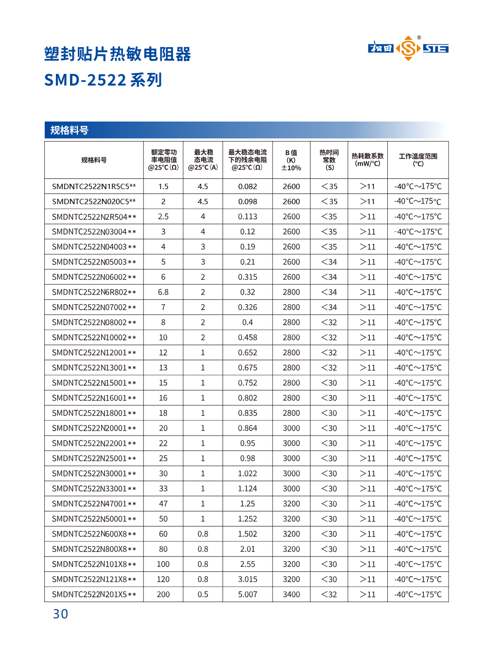
| Part number | Rated zero-power resistance at 25°C (Ω) | Maximum steady-state current at 25°C (A) | Residual resistance at maximum steady-state current, 25°C (Ω) | B value (K), ±10% | Thermal time constant (s) | Thermal dissipation factor (mW/°C) | Operating temperature (°C) |
|---|---|---|---|---|---|---|---|
| SMDNTC2522N1R5C5** | 1.5 | 4.5 | 0.082 | 2600 | <35 | >11 | -40°C~175°C |
| SMDNTC2522N020C5** | 2 | 4.5 | 0.098 | 2600 | <35 | >11 | -40°C~175°C |
| SMDNTC2522N2R504** | 2.5 | 4 | 0.113 | 2600 | <35 | >11 | -40°C~175°C |
| SMDNTC2522N03004** | 3 | 4 | 0.12 | 2600 | <35 | >11 | -40°C~175°C |
| SMDNTC2522N04003** | 4 | 3 | 0.19 | 2600 | <35 | >11 | -40°C~175°C |
| SMDNTC2522N05003** | 5 | 3 | 0.21 | 2600 | <34 | >11 | -40°C~175°C |
| SMDNTC2522N06002** | 6 | 2 | 0.315 | 2600 | <34 | >11 | -40°C~175°C |
| SMDNTC2522N6R802** | 6.8 | 2 | 0.32 | 2800 | <34 | >11 | -40°C~175°C |
| SMDNTC2522N07002** | 7 | 2 | 0.326 | 2800 | <34 | >11 | -40°C~175°C |
| SMDNTC2522N08002** | 8 | 2 | 0.4 | 2800 | <32 | >11 | -40°C~175°C |
| SMDNTC2522N10002** | 10 | 2 | 0.458 | 2800 | <32 | >11 | -40°C~175°C |
| SMDNTC2522N12001** | 12 | 1 | 0.652 | 2800 | <32 | >11 | -40°C~175°C |
| SMDNTC2522N13001** | 13 | 1 | 0.675 | 2800 | <32 | >11 | -40°C~175°C |
| SMDNTC2522N15001** | 15 | 1 | 0.752 | 2800 | <30 | >11 | -40°C~175°C |
| SMDNTC2522N16001** | 16 | 1 | 0.802 | 2800 | <30 | >11 | -40°C~175°C |
| SMDNTC2522N18001** | 18 | 1 | 0.835 | 2800 | <30 | >11 | -40°C~175°C |
| SMDNTC2522N20001** | 20 | 1 | 0.864 | 3000 | <30 | >11 | -40°C~175°C |
| SMDNTC2522N22001** | 22 | 1 | 0.95 | 3000 | <30 | >11 | -40°C~175°C |
| SMDNTC2522N25001** | 25 | 1 | 0.98 | 3000 | <30 | >11 | -40°C~175°C |
| SMDNTC2522N30001** | 30 | 1 | 1.022 | 3000 | <30 | >11 | -40°C~175°C |
| SMDNTC2522N33001** | 33 | 1 | 1.124 | 3000 | <30 | >11 | -40°C~175°C |
| SMDNTC2522N47001** | 47 | 1 | 1.25 | 3200 | <30 | >11 | -40°C~175°C |
| SMDNTC2522N50001** | 50 | 1 | 1.252 | 3200 | <30 | >11 | -40°C~175°C |
| SMDNTC2522N600X8** | 60 | 0.8 | 1.502 | 3200 | <30 | >11 | -40°C~175°C |
| SMDNTC2522N800X8** | 80 | 0.8 | 2.01 | 3200 | <30 | >11 | -40°C~175°C |
| SMDNTC2522N101X8** | 100 | 0.8 | 2.55 | 3200 | <30 | >11 | -40°C~175°C |
| SMDNTC2522N121X8** | 120 | 0.8 | 3.015 | 3200 | <30 | >11 | -40°C~175°C |
| SMDNTC2522N201X5** | 200 | 0.5 | 5.007 | 3400 | <32 | >11 | -40°C~175°C |
Historical table, including 1.5 Ω and 2 Ω options at 4.5 A. Its range and several residual-resistance/B values differ from the datasheet revised 2025-03-21; newer values have not been substituted.
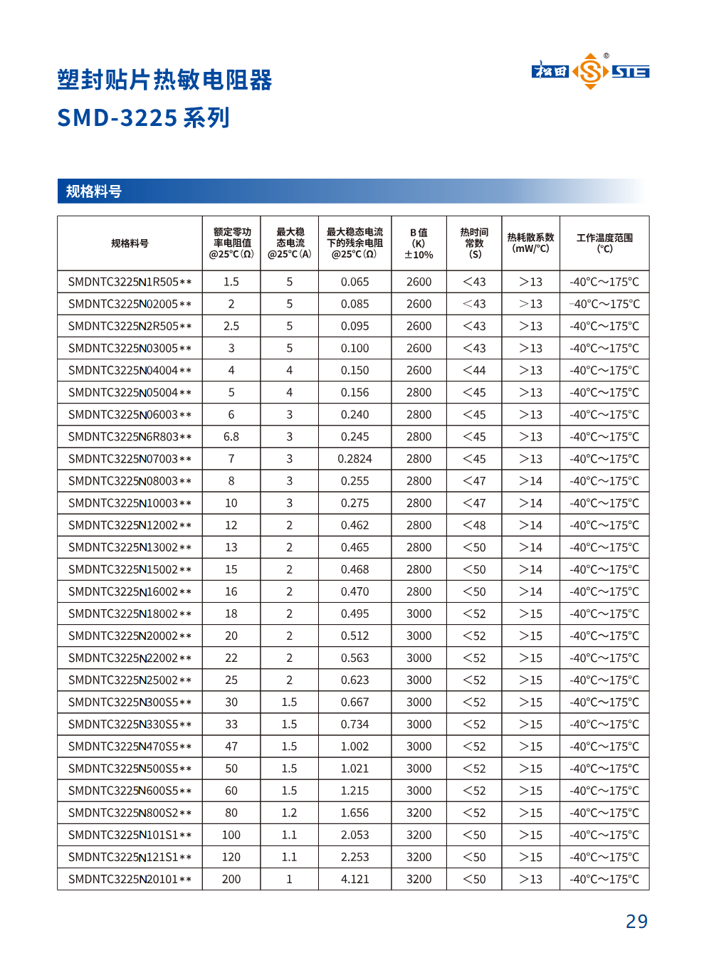
| Part number | Rated zero-power resistance at 25°C (Ω) | Maximum steady-state current at 25°C (A) | Residual resistance at maximum steady-state current, 25°C (Ω) | B value (K), ±10% | Thermal time constant (s) | Thermal dissipation factor (mW/°C) | Operating temperature (°C) |
|---|---|---|---|---|---|---|---|
| SMDNTC3225N1R505** | 1.5 | 5 | 0.065 | 2600 | <43 | >13 | -40°C~175°C |
| SMDNTC3225N02005** | 2 | 5 | 0.085 | 2600 | <43 | >13 | -40°C~175°C |
| SMDNTC3225N2R505** | 2.5 | 5 | 0.095 | 2600 | <43 | >13 | -40°C~175°C |
| SMDNTC3225N03005** | 3 | 5 | 0.100 | 2600 | <43 | >13 | -40°C~175°C |
| SMDNTC3225N04004** | 4 | 4 | 0.150 | 2600 | <44 | >13 | -40°C~175°C |
| SMDNTC3225N05004** | 5 | 4 | 0.156 | 2800 | <45 | >13 | -40°C~175°C |
| SMDNTC3225N06003** | 6 | 3 | 0.240 | 2800 | <45 | >13 | -40°C~175°C |
| SMDNTC3225N6R803** | 6.8 | 3 | 0.245 | 2800 | <45 | >13 | -40°C~175°C |
| SMDNTC3225N07003** | 7 | 3 | 0.2824 | 2800 | <45 | >13 | -40°C~175°C |
| SMDNTC3225N08003** | 8 | 3 | 0.255 | 2800 | <47 | >14 | -40°C~175°C |
| SMDNTC3225N10003** | 10 | 3 | 0.275 | 2800 | <47 | >14 | -40°C~175°C |
| SMDNTC3225N12002** | 12 | 2 | 0.462 | 2800 | <48 | >14 | -40°C~175°C |
| SMDNTC3225N13002** | 13 | 2 | 0.465 | 2800 | <50 | >14 | -40°C~175°C |
| SMDNTC3225N15002** | 15 | 2 | 0.468 | 2800 | <50 | >14 | -40°C~175°C |
| SMDNTC3225N16002** | 16 | 2 | 0.470 | 2800 | <50 | >14 | -40°C~175°C |
| SMDNTC3225N18002** | 18 | 2 | 0.495 | 3000 | <52 | >15 | -40°C~175°C |
| SMDNTC3225N20002** | 20 | 2 | 0.512 | 3000 | <52 | >15 | -40°C~175°C |
| SMDNTC3225N22002** | 22 | 2 | 0.563 | 3000 | <52 | >15 | -40°C~175°C |
| SMDNTC3225N25002** | 25 | 2 | 0.623 | 3000 | <52 | >15 | -40°C~175°C |
| SMDNTC3225N300S5** | 30 | 1.5 | 0.667 | 3000 | <52 | >15 | -40°C~175°C |
| SMDNTC3225N330S5** | 33 | 1.5 | 0.734 | 3000 | <52 | >15 | -40°C~175°C |
| SMDNTC3225N470S5** | 47 | 1.5 | 1.002 | 3000 | <52 | >15 | -40°C~175°C |
| SMDNTC3225N500S5** | 50 | 1.5 | 1.021 | 3000 | <52 | >15 | -40°C~175°C |
| SMDNTC3225N600S5** | 60 | 1.5 | 1.215 | 3000 | <52 | >15 | -40°C~175°C |
| SMDNTC3225N800S2** | 80 | 1.2 | 1.656 | 3200 | <52 | >15 | -40°C~175°C |
| SMDNTC3225N101S1** | 100 | 1.1 | 2.053 | 3200 | <50 | >15 | -40°C~175°C |
| SMDNTC3225N121S1** | 120 | 1.1 | 2.253 | 3200 | <50 | >15 | -40°C~175°C |
| SMDNTC3225N20101** | 200 | 1 | 4.121 | 3200 | <50 | >13 | -40°C~175°C |
Transcribed from the historical image, retaining its model strings, values and precision. Confirm the current datasheet before selection.
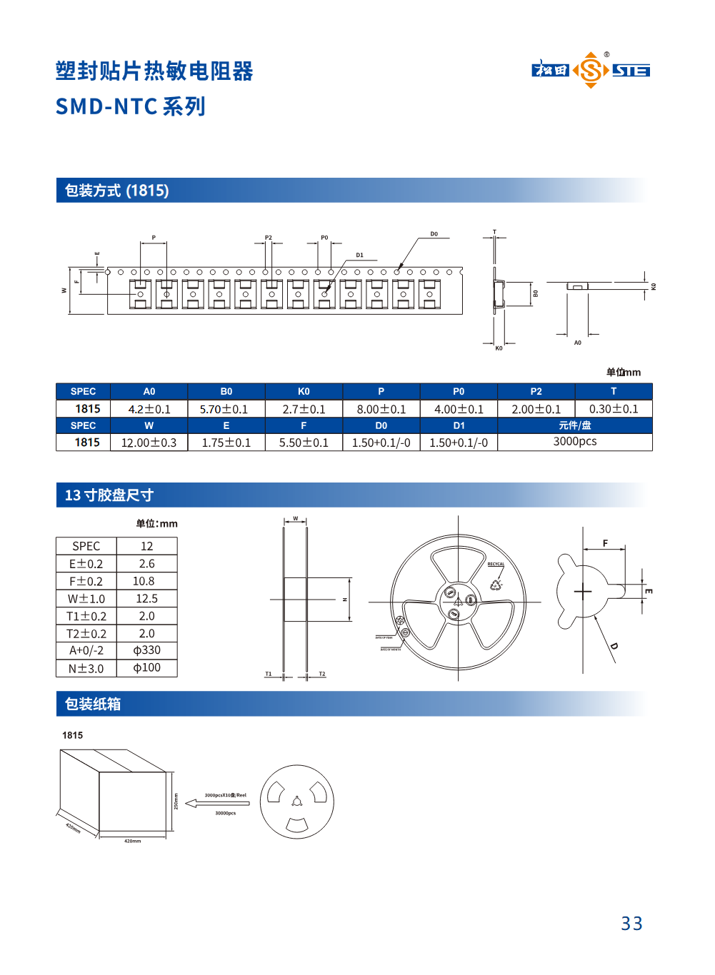
| Symbol | Dimension (mm) |
|---|---|
| E±0.2 | 2.6 |
| F±0.2 | 10.8 |
| W±1.0 | 12.5 |
| T1±0.2 | 2.0 |
| T2±0.2 | 2.0 |
| A+0/-2 | φ330 |
| N±3.0 | φ100 |
Dimensions transcribed from the source image; see the original drawing for symbol locations.
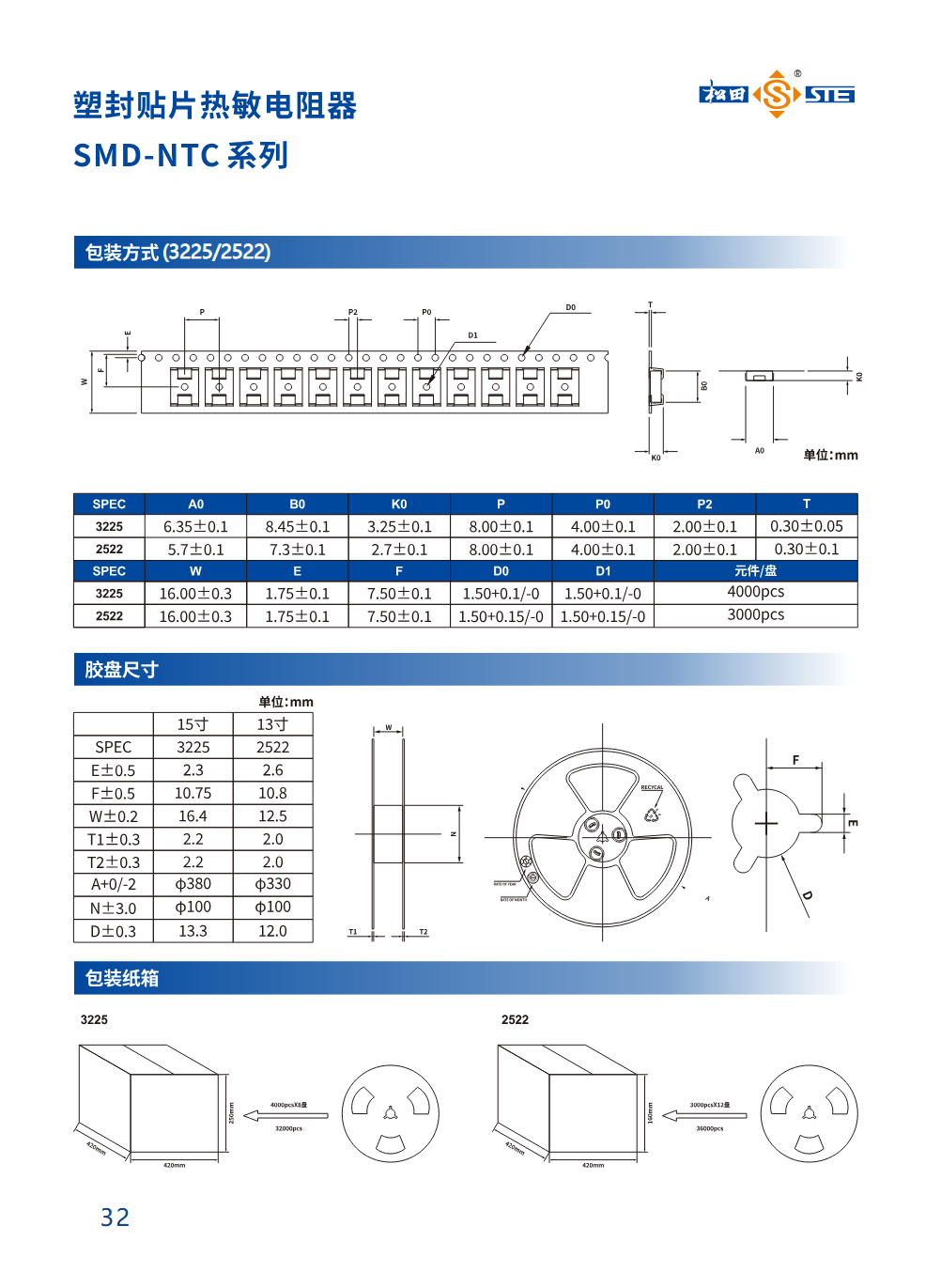
| Type | A0 | B0 | K0 | P | P0 | P2 | T |
|---|---|---|---|---|---|---|---|
| 3225 | 6.35±0.1 | 8.45±0.1 | 3.25±0.1 | 8.00±0.1 | 4.00±0.1 | 2.00±0.1 | 0.30±0.05 |
| 2522 | 5.7±0.1 | 7.3±0.1 | 2.7±0.1 | 8.00±0.1 | 4.00±0.1 | 2.00±0.1 | 0.30±0.1 |
| Type | W | E | F | D0 | D1 | Components per reel |
|---|---|---|---|---|---|---|
| 3225 | 16.00±0.3 | 1.75±0.1 | 7.50±0.1 | 1.50+0.1/-0 | 1.50+0.1/-0 | 4000 pcs |
| 2522 | 16.00±0.3 | 1.75±0.1 | 7.50±0.1 | 1.50+0.15/-0 | 1.50+0.15/-0 | 3000 pcs |
| Symbol / tolerance | 3225, 15-inch | 2522, 13-inch |
|---|---|---|
| E±0.5 | 2.3 | 2.6 |
| F±0.5 | 10.75 | 10.8 |
| W±0.2 | 16.4 | 12.5 |
| T1±0.3 | 2.2 | 2.0 |
| T2±0.3 | 2.2 | 2.0 |
| A+0/-2 | φ380 | φ330 |
| N±3.0 | φ100 | φ100 |
| D±0.3 | 13.3 | 12.0 |
Source inconsistency retained: 2522 carrier-tape W is 16.00±0.3 mm, while reel W is 12.5±0.2 mm. Confirm the packaging dimensions with the manufacturer.
Related reading cited by the original report
Chinese source titles are retained below. 更薄、更轻量,松田推出SMD系列贴片压敏电阻 松田推出SMD-X1Y1、SMC-X1Y2两款贴片Y电容 一文带你了解吉利、星星充电两家知名品牌充电桩内置的松田元件