
STE SMD NTC Thermistors Bring a Lower Profile to Compact Electronics
Original report
STE edition
Chongdiantou highlights STE’s 3225 surface mount power NTCs, with package, electrical and assembly details clarified against the formal specification.
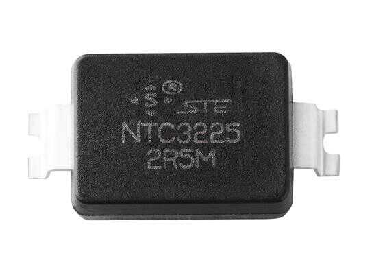
Chongdiantou reported on December 17, 2024 that STE had introduced surface mount NTC thermistors for compact consumer electronics, industrial equipment and other applications. Its coverage focused on the 3225 power NTC series: a molded package intended to bring inrush-current limiting into an automated surface mount assembly process.
The report connected this introduction with STE's wider portfolio of ceramic capacitors, film capacitors, varistors and thermistors. This English adaptation retains the product announcement while clarifying electrical and mechanical details against the formal STE specification.
A 2.5 mm nominal body height
The article compared a 5 Ω, 4 A surface mount device with a conventional leaded thermistor, describing a reduction from a reported 14.5 mm installed height to a 2.5 mm nominal body height. That comparison concerns the illustrated parts; it does not establish the dimensions of every through-hole alternative.
STE's 3225 drawing gives a body measuring 8.1 ±0.3 × 6.0 ±0.3 × 2.5 ±0.3 mm. The positive height tolerance matters when checking enclosure clearance. The package designation “3225” is not a statement that the component measures 3.2 × 2.5 mm.
Two termination styles are documented. The outward lead form and the inward lead form share the nominal body dimensions, but their terminal geometry and recommended land patterns differ. A layout change therefore needs the correct drawing rather than a comparison of body area alone. STE 3225 specification, page 4. STE 3225 specification, page 4
Electrical options for power circuits
The formal table lists the following values. These are tied to the reviewed specification, whose page-footer revision is January 17, 2024.
| Parameter | Documented value or condition |
|---|---|
| Cold resistance range | 1.5–200 Ω at 25°C |
| Example resistance | 5 Ω at 25°C |
| Maximum steady current for the 5 Ω example | 4 A at 25°C |
| Residual resistance for that example | 0.156 Ω at the stated maximum steady current and 25°C condition |
| Operating temperature range | −40 to +175°C |
The formal 1.5 Ω lower limit resolves an inconsistency in the original article, which also mentioned 1 Ω. Higher operating temperatures require the current derating given in the specification; the upper temperature limit does not mean that every option can carry its full 25°C current throughout the range.
The original report discussed temperature measurement and inrush suppression together. For the documented power NTC, the principal design question is its behaviour in the current path. Precision temperature sensing requires its own resistance-temperature accuracy and self-heating assessment; the power limiter should not automatically be presented as a precision sensor.
Packaging for automated assembly
The specification identifies packaging material meeting UL94 V-0 and support for automated assembly using the specified soldering processes. Page 7 lists 16 mm carrier tape for the inward lead form and 24 mm tape for the outward form, with 4000 pieces per reel for both. The reel drawing is nominally 15 inches.
Chongdiantou described automated placement as a way to improve assembly consistency and reduce manual handling. Those are manufacturing opportunities, while realized throughput, yield and cost depend on the board and production process.
The report also discussed heat sinks and thermally conductive adhesives. Any added thermal path needs application review: changing heat flow changes an NTC's temperature and resistance. Improved cooling should not be assumed to improve inrush limiting and operating losses simultaneously.
For a compact power supply, the announcement offers a surface mount option to evaluate alongside the required cold resistance, steady current, startup stress and restart interval. STE lists consumer, industrial, communications and automotive electronics among application areas; those descriptions do not establish automotive qualification for every variant.
Source and technical reference
Original Chinese report: 松田电子推出贴片式NTC热敏电阻器,可用于消费电子、工业设备等领域实现产品小型化, Chongdiantou, 落尘, December 17, 2024. 松田电子推出贴片式NTC热敏电阻器,可用于消费电子、工业设备等领域实现产品小型化
English adaptation prepared for STE under authorized republication and adaptation.
Figures and tables from the original report
The following figures retain their original captions, markings and historical context. Transcribed tables present the values shown in the published images; product selection should use the specifications for the selected part.
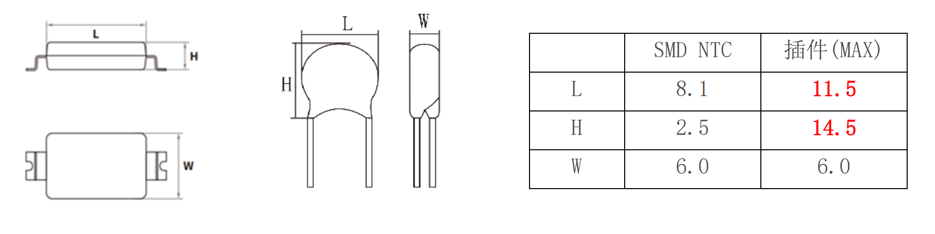
| Dimension | SMD NTC | Leaded (MAX) |
|---|---|---|
| L | 8.1 | 11.5 |
| H | 2.5 | 14.5 |
| W | 6.0 | 6.0 |
The table does not state a unit. L, H and W follow the two package drawings; the comparison applies to the illustrated samples.
| Field | Source description |
|---|---|
| Mounting type | SMD |
| Component type | NTC: negative-temperature-coefficient thermistor |
| Approximate body dimensions | 3225≈8.1×6.0 mm |
| Terminal form | W: outward; N: inward |
| Zero-power resistance codes | 010:1 Ω;1R5:1.5 Ω;100:10 Ω;101:100 Ω |
| Maximum steady-state current codes | 01:1 A;S5:1.5 A;02:2 A;03:3 A;04:4 A;05:5 A |
| Zero-power resistance tolerance | L: ±15%; M: ±20% |
Approximate dimensions do not replace the detailed dimensional tables.
| Item | Value / expression |
|---|---|
| Ambient temperature Ta | 60°C |
| Illustrative upper temperature Tu | 200°C |
| Source formula | ITa = [1 − (Ta − 25)/(Tu − 25)] × Imax = 80% Imax |
200°C is an illustrative calculation input, not a rated operating temperature for these parts. The accompanying tables specify upper limits of 155°C or 175°C. The source curve is not used to infer additional ratings.
| Item | Source statement |
|---|---|
| Source feature 1 | Molded package; the source states that the encapsulation material meets UL94-V0. |
| Source feature 2 | Compact package intended to save board space. |
| Source feature 3 | The source describes resistance to high temperature and humidity. |
| Source feature 4 | The source describes inrush-current limiting capability. |
| Source feature 5 | Reel packaging for automated assembly using lead-free reflow or wave soldering. |
| Applications listed by the source | Circuit protection, industrial equipment, communications equipment, consumer electronics and automotive electronics. |
These are statements in the historical source image, not independent verification of certification, environmental testing or automotive qualification. Check the specific device soldering profile before assembly.
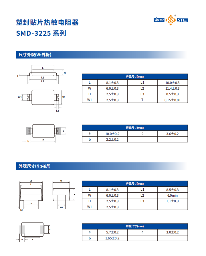
| Symbol | Dimension (mm) |
|---|---|
| L | 8.1±0.3 |
| W | 6.0±0.3 |
| H | 2.5±0.3 |
| W1 | 2.5±0.3 |
| L1 | 10.0±0.3 |
| L2 | 11.4±0.3 |
| L3 | 0.5±0.3 |
| T | 0.15±0.01 |
Dimensions transcribed from the source image; see the original drawing for symbol locations.
| Symbol | Dimension (mm) |
|---|---|
| a | 10.0±0.2 |
| b | 2.2±0.2 |
| c | 3.6±0.2 |
Dimensions transcribed from the source image; see the original drawing for symbol locations.
| Symbol | Dimension (mm) |
|---|---|
| L | 8.1±0.3 |
| W | 6.0±0.3 |
| H | 2.5±0.3 |
| W1 | 2.5±0.3 |
| L1 | 8.5±0.3 |
| L2 | 6.0 min |
| L3 | 1.1±0.3 |
Dimensions transcribed from the source image; see the original drawing for symbol locations.
| Symbol | Dimension (mm) |
|---|---|
| a | 5.7±0.2 |
| b | 1.65±0.2 |
| c | 3.0±0.2 |
Dimensions transcribed from the source image; see the original drawing for symbol locations.
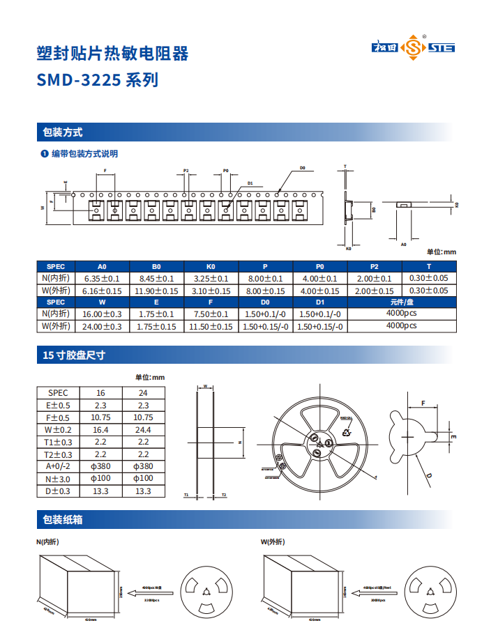
| Type | A0 | B0 | K0 | P | P0 | P2 | T |
|---|---|---|---|---|---|---|---|
| N(inward) | 6.35±0.1 | 8.45±0.1 | 3.25±0.1 | 8.00±0.1 | 4.00±0.1 | 2.00±0.1 | 0.30±0.05 |
| W(outward) | 6.16±0.15 | 11.90±0.15 | 3.10±0.15 | 8.00±0.15 | 4.00±0.15 | 2.00±0.15 | 0.30±0.05 |
| Type | W | E | F | D0 | D1 | Components per reel |
|---|---|---|---|---|---|---|
| N(inward) | 16.00±0.3 | 1.75±0.1 | 7.50±0.1 | 1.50+0.1/-0 | 1.50+0.1/-0 | 4000 pcs |
| W(outward) | 24.00±0.3 | 1.75±0.15 | 11.50±0.15 | 1.50+0.15/-0 | 1.50+0.15/-0 | 4000 pcs |
| Symbol / tolerance | Type 16 | Type 24 |
|---|---|---|
| E±0.5 | 2.3 | 2.3 |
| F±0.5 | 10.75 | 10.75 |
| W±0.2 | 16.4 | 24.4 |
| T1±0.3 | 2.2 | 2.2 |
| T2±0.3 | 2.2 | 2.2 |
| A+0/-2 | φ380 | φ380 |
| N±3.0 | φ100 | φ100 |
| D±0.3 | 13.3 | 13.3 |
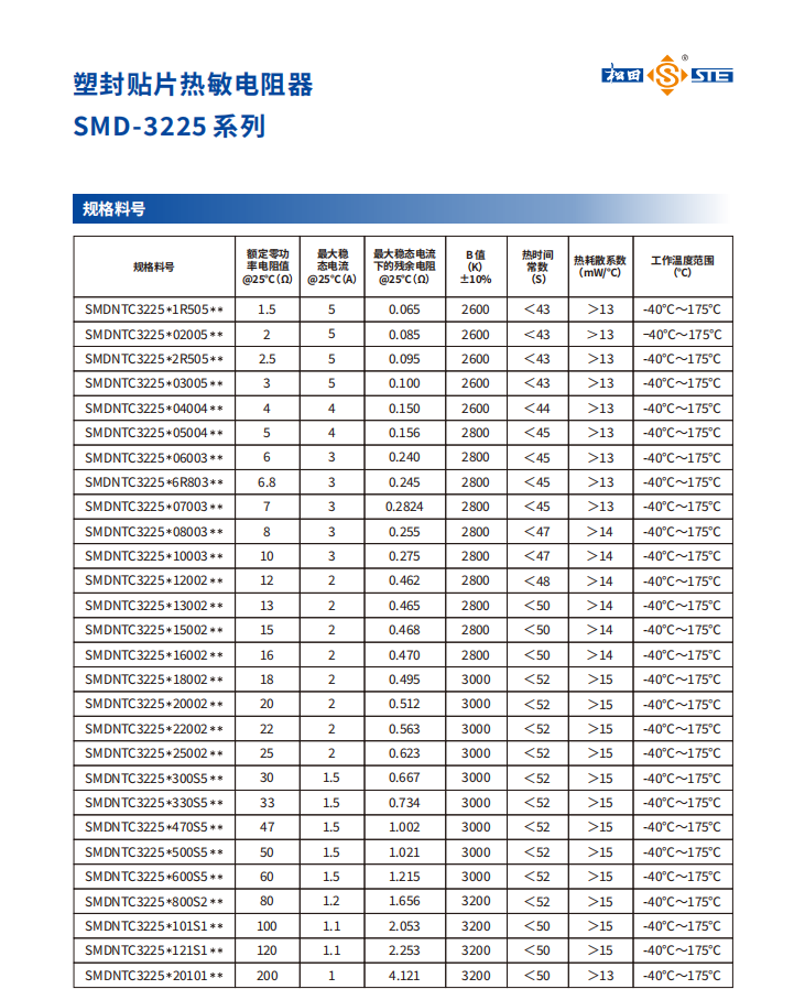
| Part number | Rated zero-power resistance at 25°C (Ω) | Maximum steady-state current at 25°C (A) | Residual resistance at maximum steady-state current, 25°C (Ω) | B value (K), ±10% | Thermal time constant (s) | Thermal dissipation factor (mW/°C) | Operating temperature (°C) |
|---|---|---|---|---|---|---|---|
| SMDNTC3225*1R505** | 1.5 | 5 | 0.065 | 2600 | <43 | >13 | -40°C~175°C |
| SMDNTC3225*02005** | 2 | 5 | 0.085 | 2600 | <43 | >13 | -40°C~175°C |
| SMDNTC3225*2R505** | 2.5 | 5 | 0.095 | 2600 | <43 | >13 | -40°C~175°C |
| SMDNTC3225*03005** | 3 | 5 | 0.100 | 2600 | <43 | >13 | -40°C~175°C |
| SMDNTC3225*04004** | 4 | 4 | 0.150 | 2600 | <44 | >13 | -40°C~175°C |
| SMDNTC3225*05004** | 5 | 4 | 0.156 | 2800 | <45 | >13 | -40°C~175°C |
| SMDNTC3225*06003** | 6 | 3 | 0.240 | 2800 | <45 | >13 | -40°C~175°C |
| SMDNTC3225*6R803** | 6.8 | 3 | 0.245 | 2800 | <45 | >13 | -40°C~175°C |
| SMDNTC3225*07003** | 7 | 3 | 0.2824 | 2800 | <45 | >13 | -40°C~175°C |
| SMDNTC3225*08003** | 8 | 3 | 0.255 | 2800 | <47 | >14 | -40°C~175°C |
| SMDNTC3225*10003** | 10 | 3 | 0.275 | 2800 | <47 | >14 | -40°C~175°C |
| SMDNTC3225*12002** | 12 | 2 | 0.462 | 2800 | <48 | >14 | -40°C~175°C |
| SMDNTC3225*13002** | 13 | 2 | 0.465 | 2800 | <50 | >14 | -40°C~175°C |
| SMDNTC3225*15002** | 15 | 2 | 0.468 | 2800 | <50 | >14 | -40°C~175°C |
| SMDNTC3225*16002** | 16 | 2 | 0.470 | 2800 | <50 | >14 | -40°C~175°C |
| SMDNTC3225*18002** | 18 | 2 | 0.495 | 3000 | <52 | >15 | -40°C~175°C |
| SMDNTC3225*20002** | 20 | 2 | 0.512 | 3000 | <52 | >15 | -40°C~175°C |
| SMDNTC3225*22002** | 22 | 2 | 0.563 | 3000 | <52 | >15 | -40°C~175°C |
| SMDNTC3225*25002** | 25 | 2 | 0.623 | 3000 | <52 | >15 | -40°C~175°C |
| SMDNTC3225*300S5** | 30 | 1.5 | 0.667 | 3000 | <52 | >15 | -40°C~175°C |
| SMDNTC3225*330S5** | 33 | 1.5 | 0.734 | 3000 | <52 | >15 | -40°C~175°C |
| SMDNTC3225*470S5** | 47 | 1.5 | 1.002 | 3000 | <52 | >15 | -40°C~175°C |
| SMDNTC3225*500S5** | 50 | 1.5 | 1.021 | 3000 | <52 | >15 | -40°C~175°C |
| SMDNTC3225*600S5** | 60 | 1.5 | 1.215 | 3000 | <52 | >15 | -40°C~175°C |
| SMDNTC3225*800S2** | 80 | 1.2 | 1.656 | 3200 | <52 | >15 | -40°C~175°C |
| SMDNTC3225*101S1** | 100 | 1.1 | 2.053 | 3200 | <50 | >15 | -40°C~175°C |
| SMDNTC3225*121S1** | 120 | 1.1 | 2.253 | 3200 | <50 | >15 | -40°C~175°C |
| SMDNTC3225*20101** | 200 | 1 | 4.121 | 3200 | <50 | >13 | -40°C~175°C |
Transcribed from the historical image, retaining its model strings, values and precision. Confirm the current datasheet before selection.