Spring 2025 Asia Charging Expo Preview: STE and Six Component Suppliers
Original report
STE edition
A historical exhibition preview covers STE safety capacitors alongside thermal materials, optocouplers, power devices and connectors from six other suppliers.
Published in December 2024, this Chongdiantou preview introduced seven suppliers planning to exhibit at the Spring 2025 Asia Charging Expo. It covered five component categories relevant to higher-power charging: thermal materials, optocouplers, capacitors, power devices and connectors. STE's section concerned surface-mount Y safety capacitors.
The event was scheduled for March 28, 2025 at the Shenzhen Qianhai International Conference Center. The following account retains that historical setting and the complete supplier and product coverage. Product and certification statements are attributed to the original report rather than presented as a new independent test.
Hanyu: two-component thermal gel
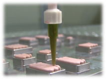
Dongguan Hanyu Thermal Technology planned to show HN-20AB-NH, a customizable two-component thermal gel for high-power PD supplies, notebook chargers, PC power supplies and other adapters.
The source describes an A/B formulation mixed at a 1:1 ratio without reaction by-products. It says the formulation incorporates nanomaterials intended to support thermal radiation, and is intended to distribute heat among internal components while providing electrical insulation and thermal contact.
The material can be dispensed in an automated process and used to fill gaps, bond and secure components. Viscosity and curing time can be tailored. The article emphasizes low deformation force, three-dimensional contact and easier removal for repair than some RTV or epoxy adhesives. Its statements about lower thermal resistance at the same thermal conductivity are supplier claims without a common comparative test method supplied in the article.
Jingtai: KL101X and KL817X optocouplers
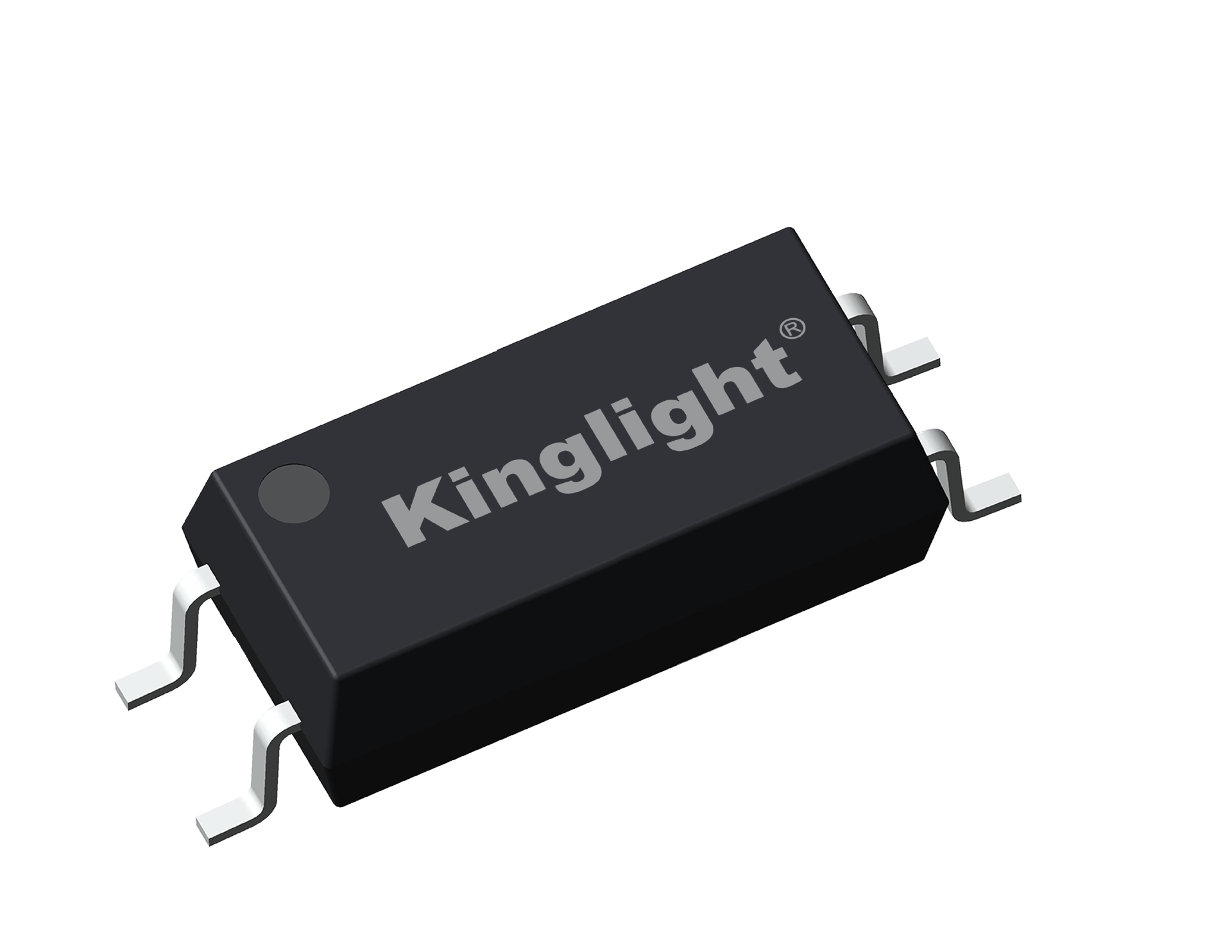
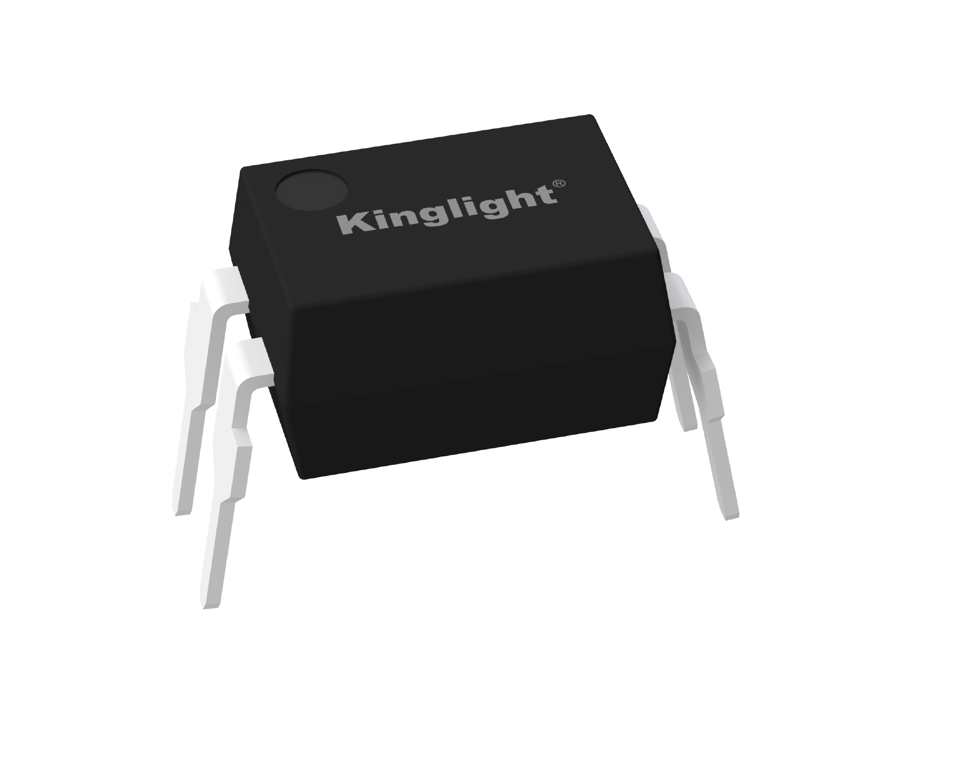
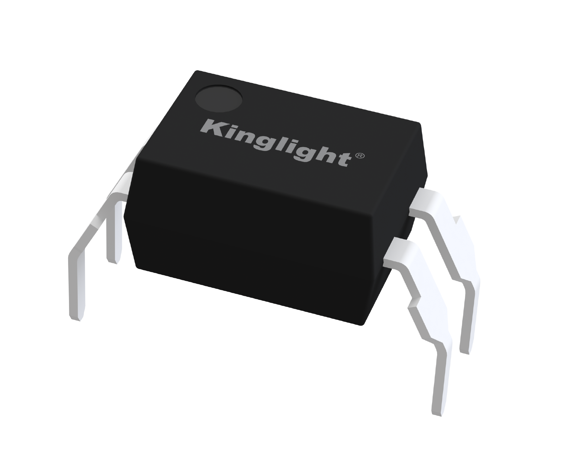
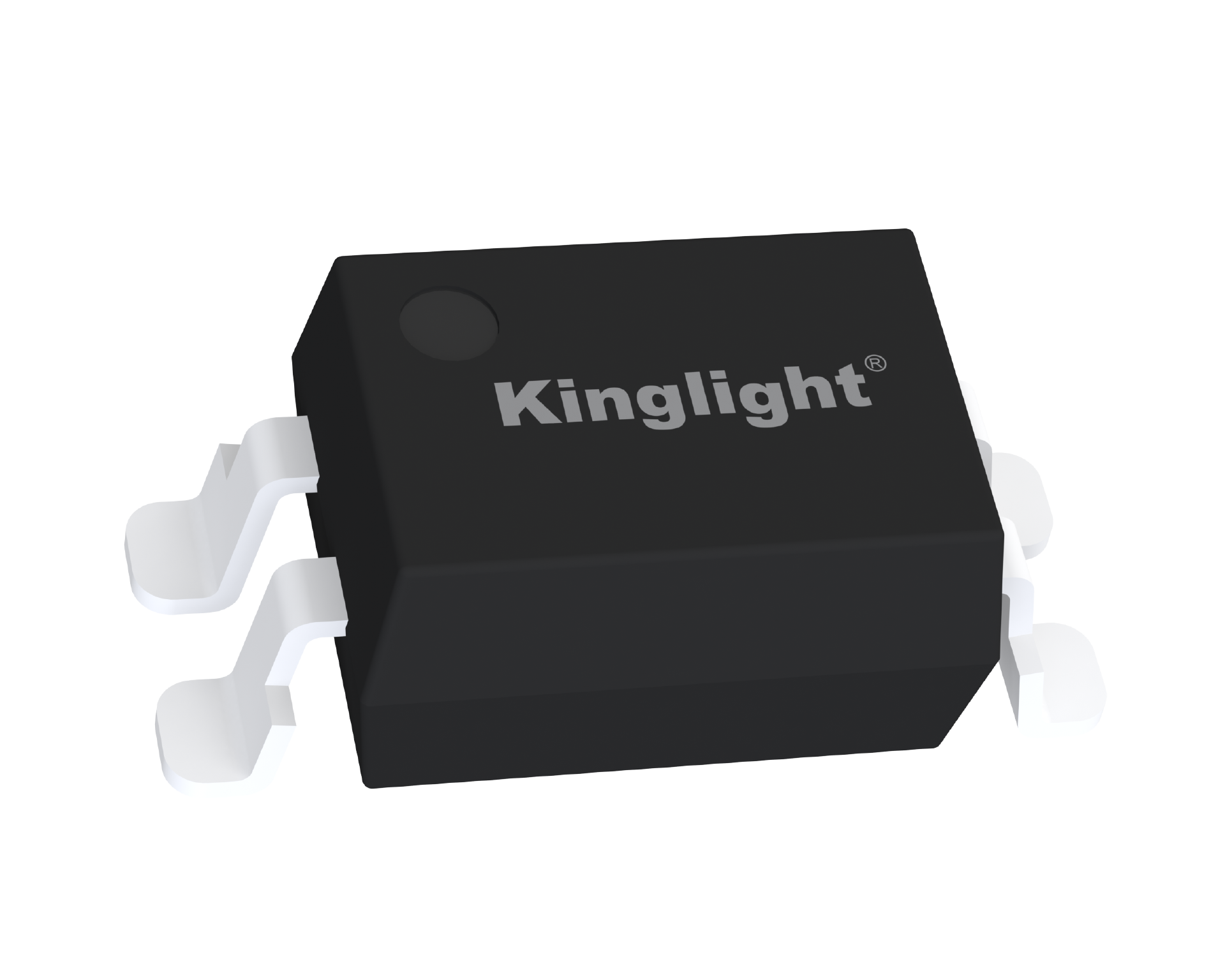
Suzhou Jingtai Optoelectronics introduced two optocoupler families. KL101X uses a four-pin surface-mount LSOP package, positioned for small size and high isolation voltage. KL817X is offered in four-pin DIP, DIP-M and SMD forms, with different package-spacing and assembly choices.
The article describes optically coupled signal transfer between input and output circuits with different voltage references or impedances. It lists AC–DC and DC–DC isolation, low-speed analog feedback for voltage, temperature, humidity or speed, and isolation or level conversion for MCU, PLC and DSP PWM and I/O signals. It also names RS-485 and RS-232 communications and IGBT or MOSFET drive isolation as application categories.
Industrial automation, power electronics, consumer products, medical devices, automotive electronics and telecommunications appear among the intended markets. A particular device must still be selected against its electrical and safety ratings.
STE: SMD-X1Y1 and SMC-X1Y2 safety capacitors
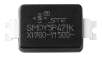
The source introduced STE’s Shantou bonded-zone company, with ceramic capacitors, film capacitors, varistors and thermistors in its product range. The exhibition preview focused on SMD-X1Y1 and SMC-X1Y2 surface-mount Y capacitors.
The source describes approximately 2.5 mm component height and a flame-retardant epoxy enclosure meeting UL94 V-0. It reports 85°C/85% RH testing and 1,000 thermal-shock cycles associated with AEC-Q200 test requirements. These statements concern the reported tests; they do not establish that every variant is qualified to the entire AEC-Q200 program.
For SMD-X1Y1, the article discusses dimensions intended to meet the relevant IEC 60384-14 Y1 creepage and clearance requirements, and reports VDE/ENEC certification. It also makes a first-certificate claim. That historical claim remains attributable to the publisher and should be checked against the certificate and its issue date before being reused as an independent statement.
The packaging approach places the ceramic element horizontally, in contrast with a traditional upright leaded configuration, and supports surface-mount assembly. The article links this to reduced height, more consistent external dimensions and production automation. It lists interference suppression, coupling, bypass and filtering among the applications. Safety class, position in the circuit and the exact part's approval determine suitability.
Fangzhou Microelectronics: high-voltage integrated regulators and power devices
Chengdu Fangzhou Microelectronics planned to exhibit its HVIR high-voltage integrated regulator family and industrial and consumer power-device solutions.
The source describes HVIR devices as converting a high input voltage to a regulated lower voltage for power-supply ICs or other circuits. Its accompanying product table gives maximum input voltages of 180 V for AKZ16V18R, 190 V for AKZ25V19R, 200 V for AKZ35V20R and 600 V for AKZ05V60R. These part-specific table values differ from the article’s narrative, which groups the first three devices under 190 V.
Features listed include temperature compensation, output accuracy, reduced output variation with load, and compact SOT-23, SOT-89 and SOT-223 packages. Below the regulation threshold, output approximately follows input; above it, the output is clamped to the device's threshold. The article discusses using this behavior in overvoltage or overcurrent protection, subject to the surrounding circuit.
Other named products are the industrial DMX(S)1072 and DMD4523E families, described as alternatives to traditional JFET functions in transient protection, with an AEC-Q101 statement. Consumer examples include DMZ6005E and DMZ85200 for PD3.1 or other high-power supplies. The report also mentions a new generation of 1,200 V silicon-carbide devices and further products under development or pilot production. It provides no like-for-like evidence for its international performance-ranking language.
KYET: boxed and epoxy-coated film capacitors
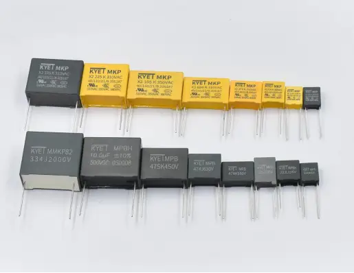
Dongguan KYET's preview covers boxed film and safety capacitors and epoxy-encapsulated film capacitors.
The reported X2 portfolio offers 310, 350 and 380 VAC ratings. The article describes selected metallized films, heat-resistant cases and epoxy filling, and reports CQC testing against GB/T 6346.14-2023, together with UL and ENEC approvals.
The company separates products for interference suppression from versions designed for capacitive-dropper circuits. Compact 7.5 mm and 10 mm pitch options and low-noise high-frequency fast-charging variants are mentioned. Higher-voltage 350/380 VAC types are described with lead pitches up to 37.5 mm, for larger inverter, energy-storage and EV-charging supplies. An 85°C/85% RH version targets reduced capacitance loss during humid-heat exposure.
The source gives temperature ranges of −55 to +125°C or −40 to +110°C, depending on the product. It discusses high insulation, low loss, self-healing, moisture resistance and current or pulse capability as family characteristics.
For epoxy-coated film capacitors, it describes liquid-epoxy impregnation or a powder-coating process selected for the application, together with customized development. These products cover high-frequency, DC, AC, pulse and high-current circuits, and suitable versions for capacitive-dropper use. The article's coating-process wording is retained at a general level because it is not a complete manufacturing specification.
JingQin: four surface-mount protection families
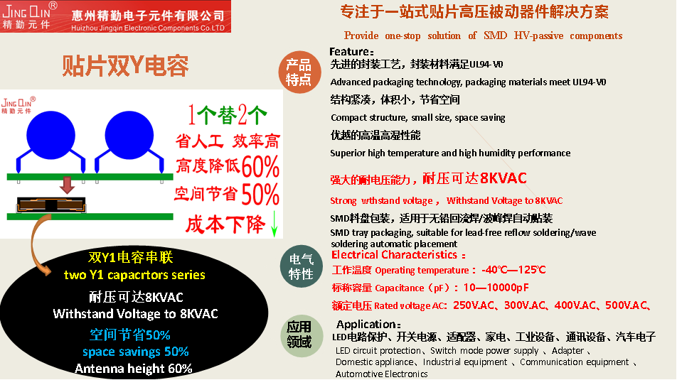
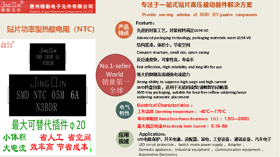
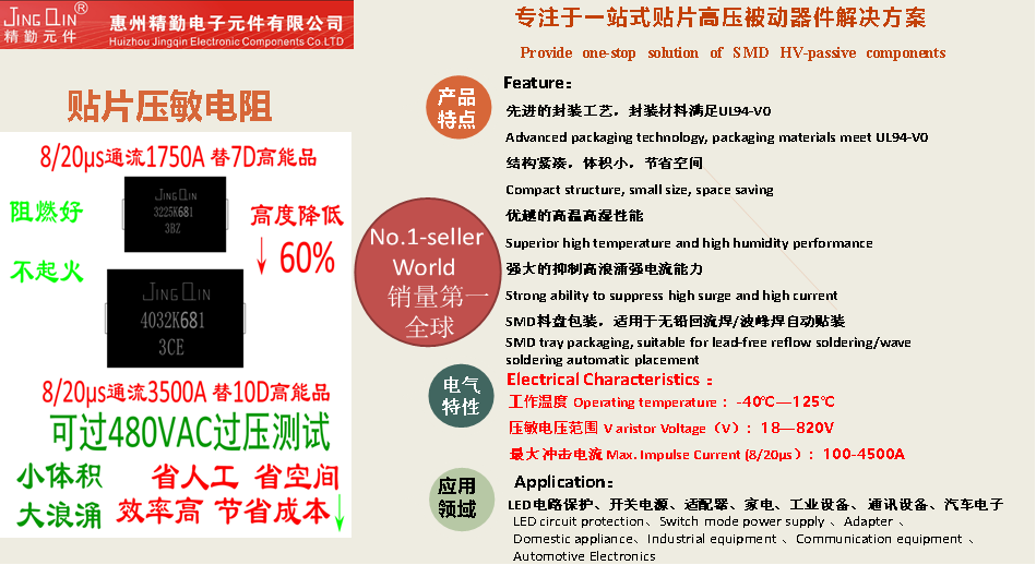
Huizhou JingQin presented four types of surface-mount component. The source describes compact UL94 V-0 packages and compatibility with automated assembly.
| Product group | Parameters stated in the report | Context |
|---|---|---|
| Y safety capacitors | −40 to +125°C; 10–10,000 pF; 250–500 VAC | LED supplies, switching supplies, industrial and communications equipment; lead-free reflow |
| Dual-Y safety capacitors | −40 to +125°C; 10–10,000 pF; 250–500 VAC; reported 8 kVAC withstand | Compact dual-element approach; automotive electronics also named |
| Power thermistors | −40 to +175°C; zero-power resistance 1.5–200 Ω; maximum steady-state current 0.1–8 A | Inrush limiting; reflow and wave assembly discussed |
| Varistors | −40 to +125°C; varistor voltage 18–820 V; maximum surge current 100–4,500 A | Protection of supplies, adapters, appliances, industrial and communications equipment |
The article reports a 60% efficiency increase and 50% space saving for its dual-Y description, but does not define the baseline, production process or measurement method. Those comparative percentages therefore remain source claims, not a measured result established by this adaptation.
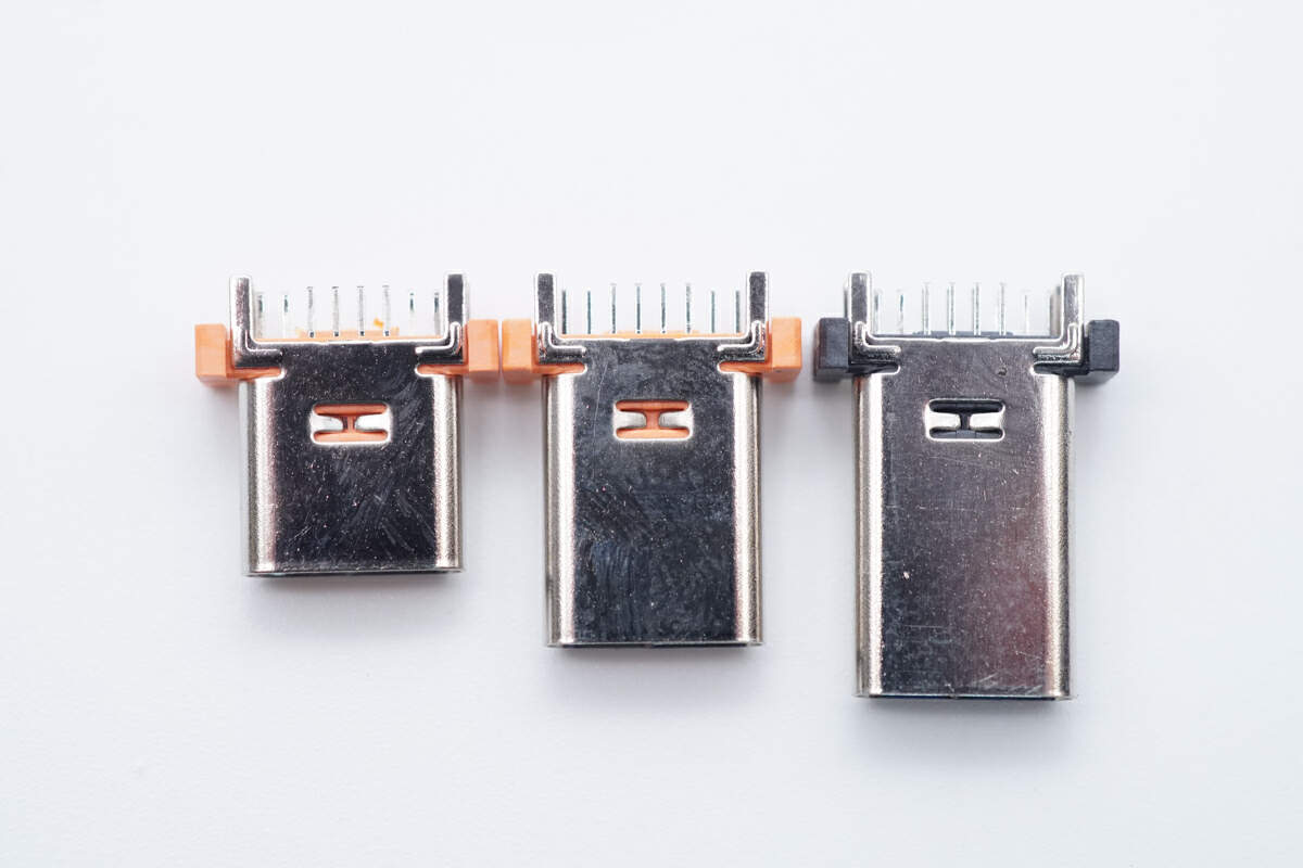
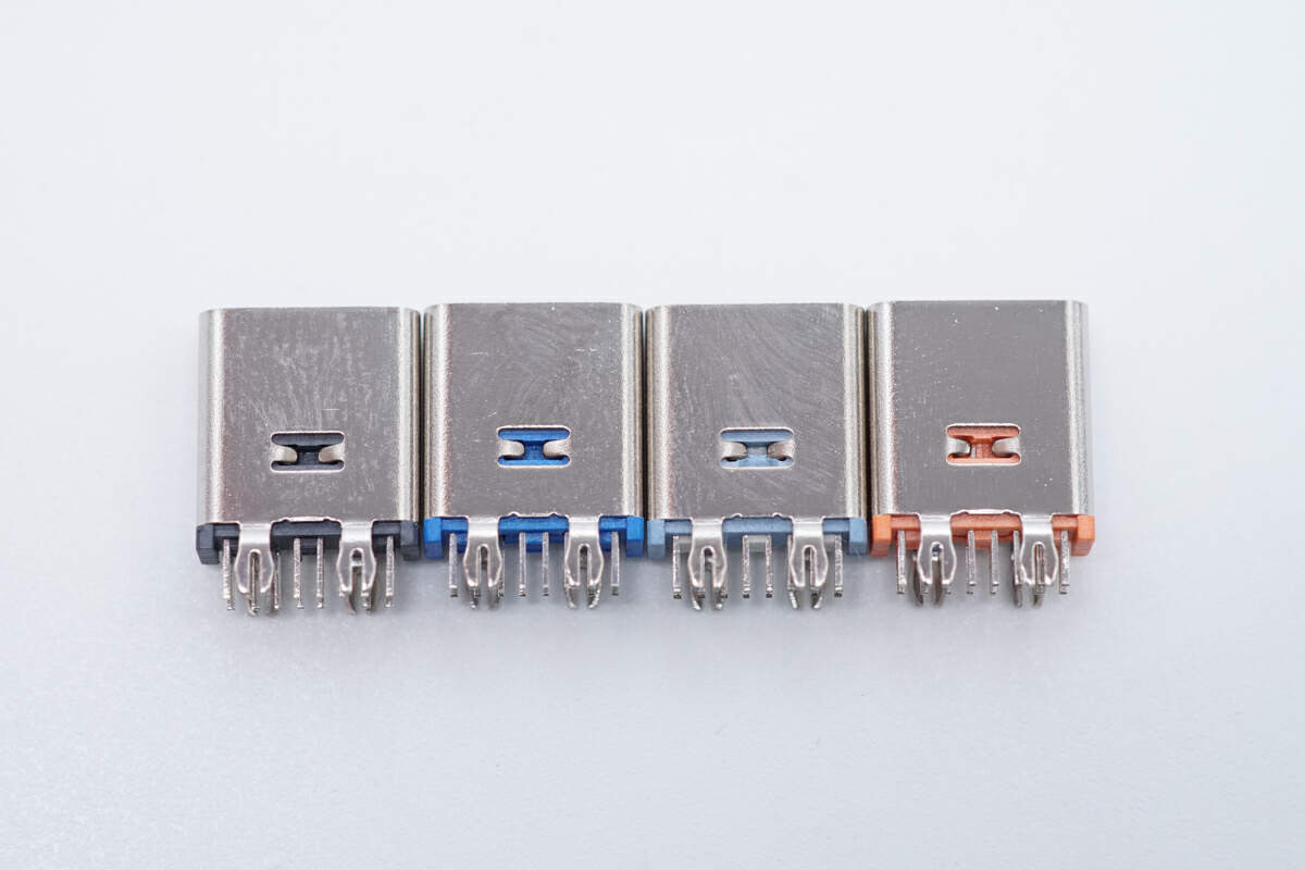
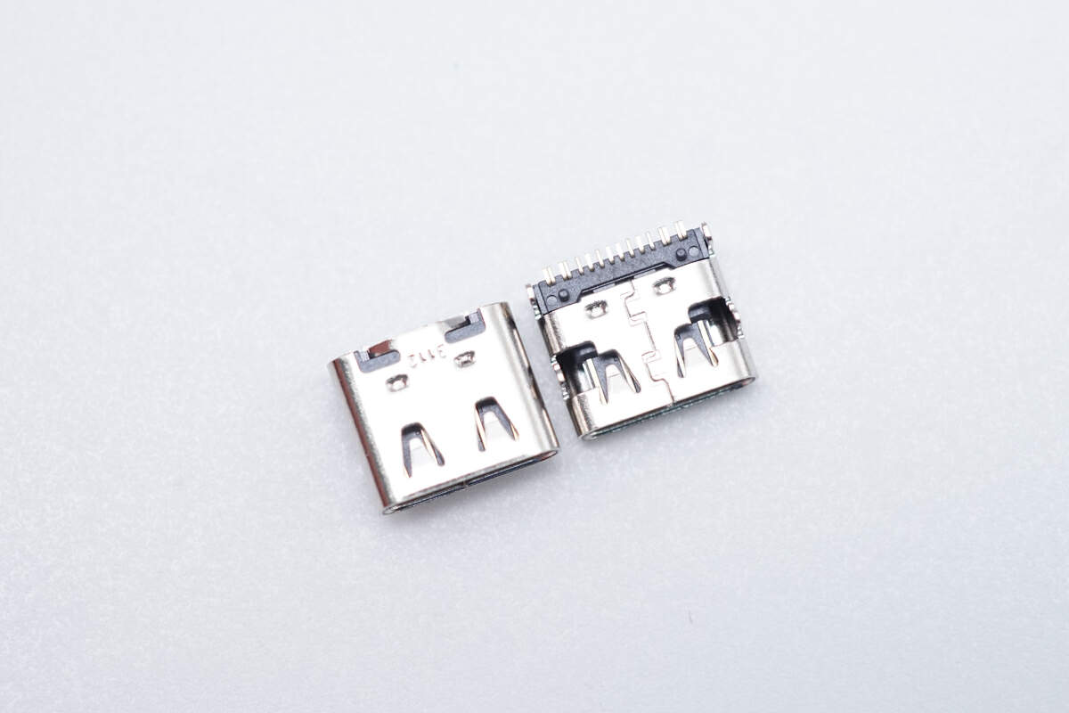
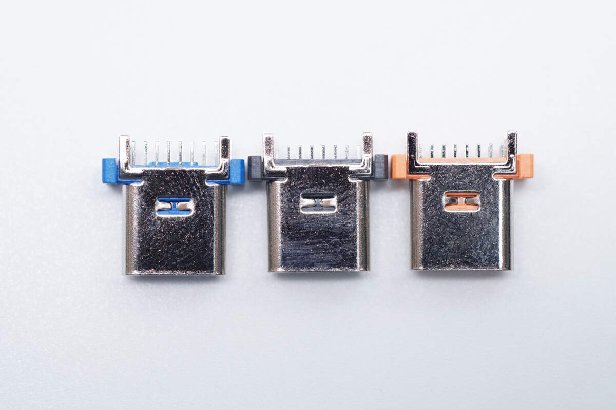
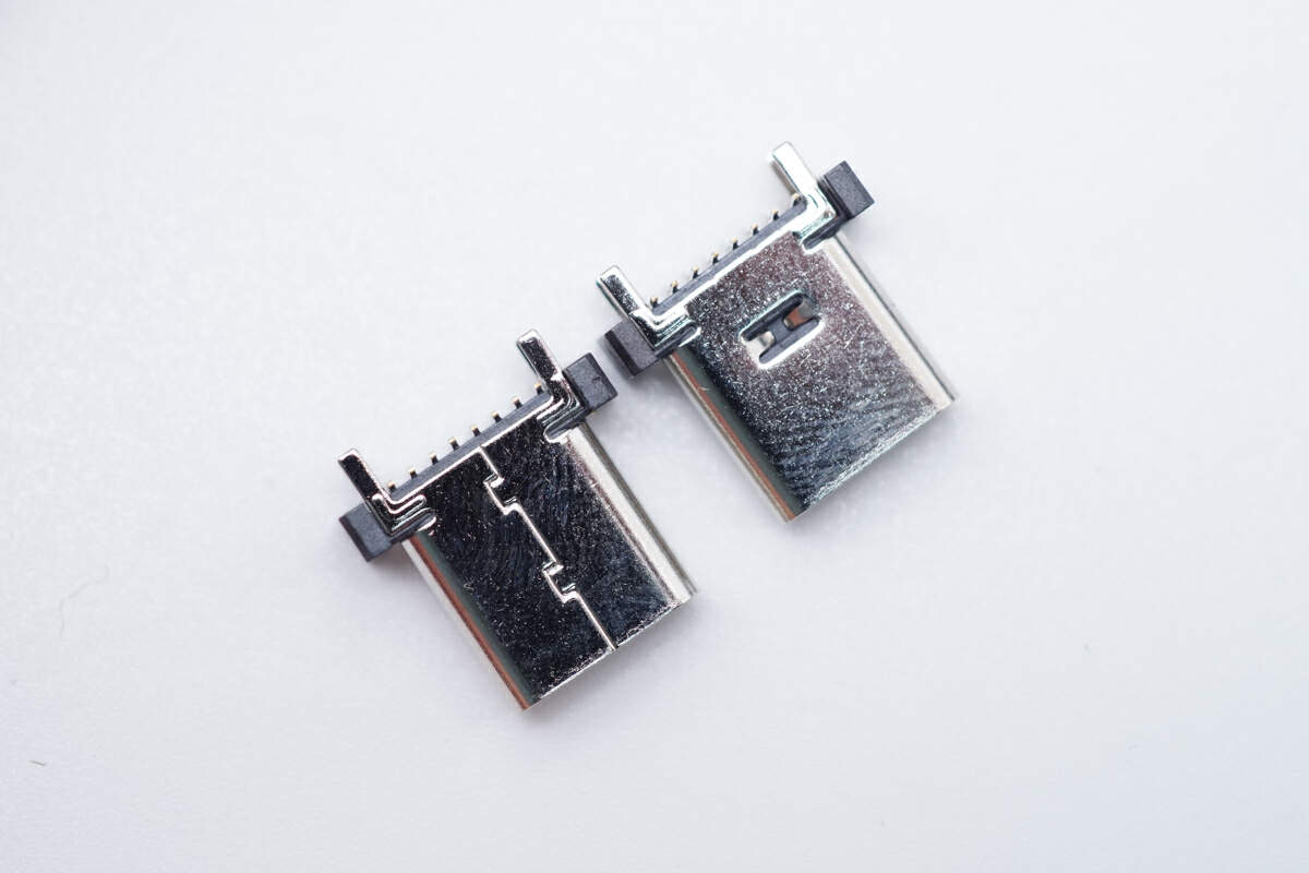
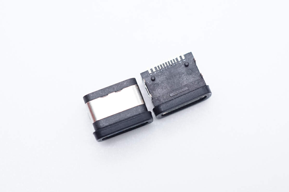
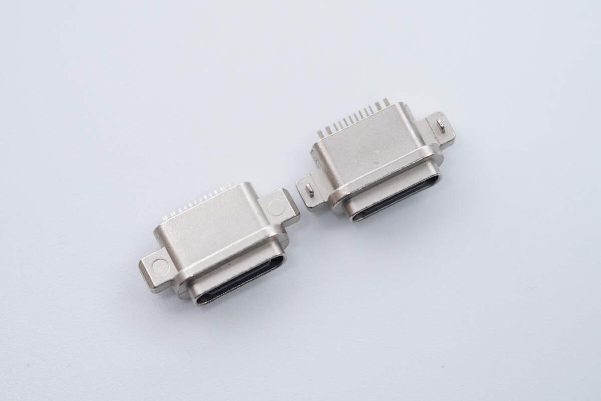
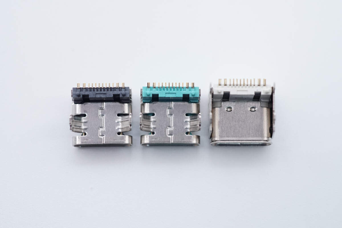
Taipusheng: eight USB-C receptacle designs
The connector supplier's section identifies Shenzhen Taipusheng Technology. The introduction reverses two syllables in the supplier’s name; this adaptation follows Taipusheng in the detailed supplier heading.
The eight designs shown are:
- 12–14-pin upright through-hole USB-C receptacle.
- 14-pin upright through-hole USB-C receptacle.
- 16-pin board-top receptacle with spring feature, described as certified in the source.
- 16-pin upright through-hole receptacle, correcting the source's apparent “UAB-C” typographical error.
- 16-pin upright surface-mount receptacle.
- 16-pin waterproof surface-mount receptacle.
- 16-pin waterproof mid-mount receptacle.
- 16-pin raised board-top receptacle.
The report positions these options for phones, tablets, power banks, small appliances and underwater cameras, including applications with frequent mating cycles or water-resistance requirements. It does not supply a shared IP rating or mating-cycle figure for all eight designs.
Historical event notice
The original closes with an invitation to the March 28, 2025 exhibition and an organizer contact section for prospective exhibitors and speakers. That recruitment notice is preserved in the Chinese source record as historical material. For reference, the organizer's published general contact was info@chongdiantou.com; this page does not present the expired event as accepting new registrations.
Figures and tables from the original report
The following figures retain their original captions, markings and historical context. Transcribed tables present the values shown in the published images; product selection should use the specifications for the selected part.
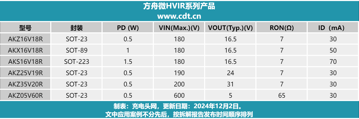
| Model | Package | PD (W) | VIN maximum (V) | VOUT typical (V) | RON (Ω) | ID (mA) |
|---|---|---|---|---|---|---|
| AKZ16V18R | SOT-23 | 0.5 | 180 | 16.5 | 7 | 30 |
| AKX16V18R | SOT-89 | 1 | 180 | 16.5 | 7 | 50 |
| AKS16V18R | SOT-223 | 1.5 | 180 | 16.5 | 7 | 70 |
| AKZ25V19R | SOT-23 | 0.5 | 190 | 24 | 7 | 30 |
| AKZ35V20R | SOT-23 | 0.5 | 200 | 31 | 7 | 30 |
| AKZ05V60R | SOT-23 | 0.5 | 600 | 5 | 65 | 30 |
The source table was prepared by Chongdiantou and updated on December 2, 2024. Symbols and values are retained as printed.
| Part number | BVDSX (V) | ID (A) | VTH (V) | RDS(ON), typical (Ω) | RDS(ON), maximum (Ω) | Package | Configuration |
|---|---|---|---|---|---|---|---|
| DMZ1015E/DMX1015E | 100 | 0.1 | −27 | / | 30 | SOT-23/SOT-89 | Depletion mode, with ESD |
| DMZ1315E/DMX1315E | 130 | 0.1 | −27 to −17 | 11 | 30 | SOT-23/SOT-89 | Depletion mode, with ESD |
| DMZ1315EL/DMX1315EL | 130 | 0.1 | −20 to −13 | 15 | 30 | SOT-23/SOT-89 | Depletion mode, with ESD |
| DMZ1521E | 150 | 0.2 | −5.0 to −7.0 | 10 | 15 | SOT-23 | Depletion mode, with ESD |
| DMZ6005E | 600 | 0.02 | −1.5 to −3.3 | 500 | 700 | SOT-23 | Depletion mode, with ESD |
| DMZ6012E | 600 | 0.04 | −1.5 to −3.3 | 110 | 150 | SOT-23 | Depletion mode, with ESD |
| DME6010D | 600 | 0.02 | −1.5 to −3.3 | 500 | 700 | SOP-7 | Depletion mode, with ESD |
| DME6010D | 100 | 0.1 | −27 | / | 30 | SOP-7 | Depletion mode, with ESD |
| DMZ85200E | 850 | 0.01 | −1.2 to −3.3 | / | 200 | SOT-23 | Depletion mode, with ESD |
| AKF30N5P0SX | 30 | 59 | 2.0 to 1.0 | 0.0039 | 0.0052 | PDFN3×3 | Enhancement-mode MOSFET |
| FTZ15N35G/FTX15N35G | 350 | 0.2 | 3.0 to 1.0 | 8 | 15 | SOT-23/SOT-89 | Enhancement-mode MOSFET |
The ordering of VTH range endpoints and “/” placeholders are retained from the source; measurement conditions are not provided in the image. DME6010D has two parameter subrows, shown separately here. A footer also lists 20/40/60/85/100/150/200/350 V enhancement-mode MOSFETs with ESD.

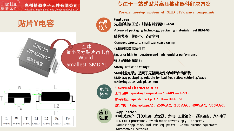
| L | W | T | L1 | L2 | FL | FW |
|---|---|---|---|---|---|---|
| 7.0±0.1 | 5.6±0.1 | 2.4±0.2 | 9.5±0.3 | 8.3±0.3 | 0.6±0.3 | 2.5±0.3 |
Dimension symbols correspond to the source drawing.
| Parameter | Source value |
|---|---|
| Operating temperature | −40°C–125°C |
| Nominal capacitance | 10–10000 pF |
| Rated AC voltage | 250 / 300 / 400 / 500 VAC |
These are overview values; the image does not map each capacitance and voltage to a specific model.
| Item | Source description |
|---|---|
| Packaging material | Source states UL94-V0 compliance |
| Packaging and assembly | SMD tray packaging; source describes lead-free reflow / wave soldering and automatic placement |
| Applications | LED circuit protection, switching power supplies, adapters, domestic appliances, industrial equipment, communications equipment and automotive electronics |
Materials and applications are claims in the source image, not evidence of end-product approval or qualification for a specific automotive application.