
Do not select from R25 alone
An R25 value does not define the temperature conversion. Obtain the nominal B value, reference temperatures, R/T curve, ±°C band and drift of the production part number for the firmware coefficients.
| R25 | 0.1–100 kΩ |
|---|---|
| Operating temperature | −55 °C to +220 °C |
| Body size (L × D) | 3.6 × 1.5 mm / 1.8 × 1.1 mm |
| Thermal time constant, static air | ≤10 s / ≤5 s |
| R25 tolerance | ±1% to ±10% |
| Rated power (25 °C) | ≤10 mW / ≤5 mW |
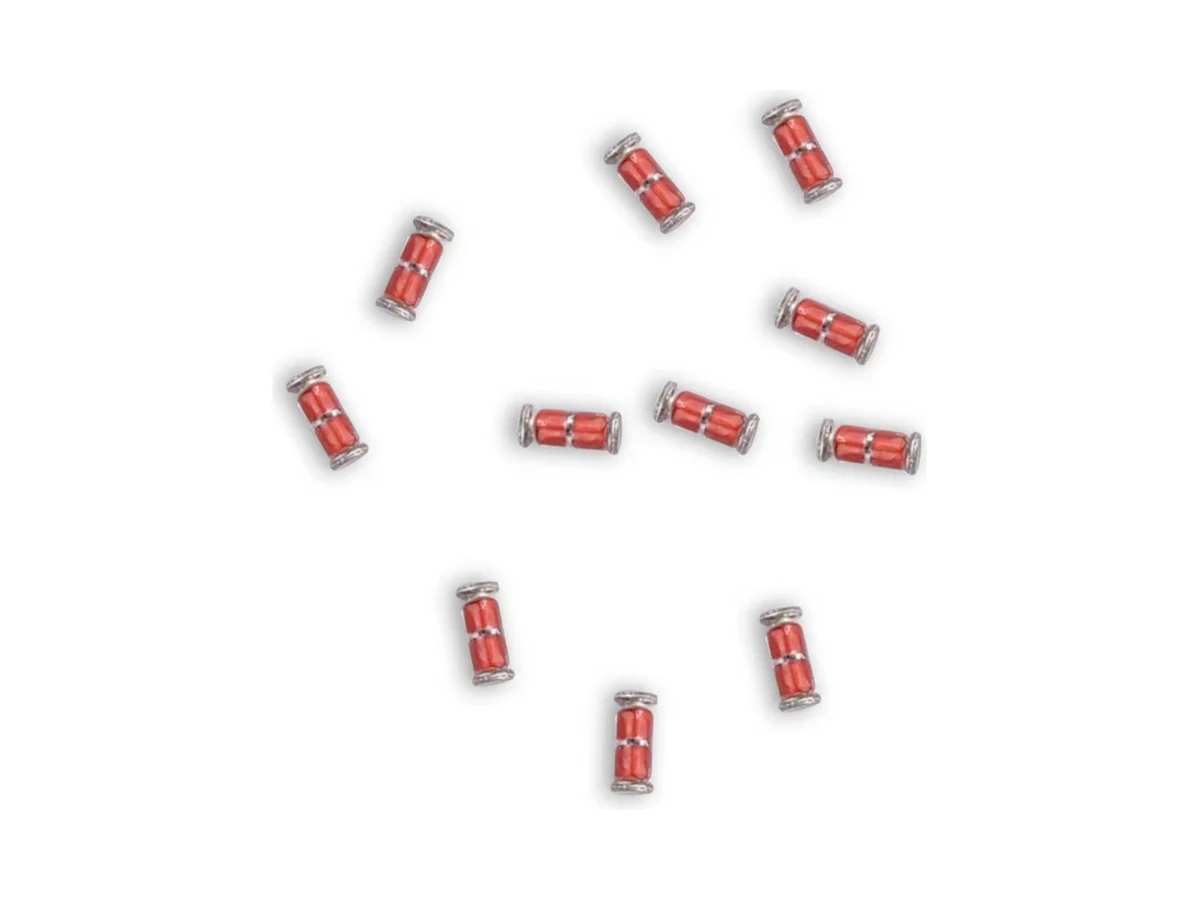
Leadless glass-encapsulated NTC thermistors for temperature sensing and compensation. Two body sizes, R25 0.1–100 kΩ, operating temperature −55 °C to +220 °C.
Part-number list on request. Download the datasheet or send us your specification.
Send your specificationDatasheets, technical documents and approval certificates for this series. English editions of documents marked “Chinese” are available on request.
Leadless cylindrical glass-encapsulated NTC thermistors for temperature measurement and compensation. Two sizes: MF59A, L 3.6 × D 1.5 mm, and MF59B, L 1.8 × D 1.1 mm. R25 0.1–100 kΩ, tolerance ±1% to ±10%. Operating temperature −55 °C to +220 °C; thermal time constant ≤10 s (MF59A) or ≤5 s (MF59B) in static air.
| Function | Leadless NTC thermistor for temperature measurement or compensation; zero-power resistance decreases as the element temperature rises |
|---|---|
| Construction | Cylindrical leadless glass body with conductive end layers; sizes MF59A and MF59B |
| Environmental compliance | RoHS and REACH compliant. Halogen status and material declarations on request. |
| Packing | Bulk. Tape and reel on request. |
| Rated zero-power resistance R25 | 0.1–100 kΩ (MF59A and MF59B) |
| R25 tolerance | ±1% · ±2% · ±3% · ±5% · ±10% |
| R25 code examples | 102 = 1 kΩ · 103 = 10 kΩ · 104 = 100 kΩ |
| Available values | R25, B-value and tolerance combinations for MF59A and MF59B: availability on request. |
| B-value tolerance | ±0.5% · ±1% |
| B-value definition | Defined from the zero-power resistances at T1 = 298.15 K and T2 = 323.15 K or 358.15 K |
| Temperature accuracy | R25 and B tolerances do not state a ±°C accuracy. Calculate the temperature error from the R/T table of the selected part. |
| Zero-power resistance | DC resistance at temperature t, measured at a power low enough that any further reduction changes the resistance by less than 0.1% |
| Thermal data, MF59A | τ ≤10 s · δ ≥2 mW/°C in static air · rated power ≤10 mW at 25 °C |
| Thermal data, MF59B | τ ≤5 s · δ ≥1 mW/°C in static air · rated power ≤5 mW at 25 °C |
| Operating temperature | −55 °C to +220 °C. Temperature grade and end-termination limits by part number on request. |
| Thermal time constant, definition | Time to reach 63.2% of the element temperature change, under zero-power conditions |
| Dimensions, MF59A | L 3.6 ±0.3 mm · D 1.5 ±0.2 mm |
| Dimensions, MF59B | L 1.8 ±0.3 mm · D 1.1 ±0.2 mm |
| Glass seal | Glass encapsulated; no hermetic-seal rating is specified. |
| Package outline | MELF-style cylindrical body; no SOD-80, MiniMELF, MicroMELF, EIA or JEDEC outline is specified. Do not derive a standard footprint from the body shape. |
| Storage | ≤35 °C · ≤70% RH · 12 months · keep the original package closed and reseal after opening |
| Corrosive atmospheres | Hydrogen chloride, hydrogen sulfide and sulfur compounds can degrade solderability. Avoid exposure. |
| Battery packs | Validate isolation, flame and fault behavior, cell contact, adhesive, vibration and drift in the pack. |
| Further data on request | Nominal B value, reference temperatures and R/T table · power derating versus ambient temperature, excitation voltage and current, allowed self-heating · max. working voltage and current, insulation resistance and dielectric withstand · end-termination material, plating and solderability class · moisture and insulation data · recommended land pattern, stencil and solder volume · reflow profile, max. body temperature and time, number of cycles, rework method · MSL rating and floor life · dry-heat endurance, damp heat with bias, thermal-shock, board-bend, vibration, drop, terminal-strength, solderability and resistance-to-soldering-heat results |
Ranges by dielectric, package and lead style within this series.
| Variant | Body dimensions | R25 | Temperature range / thermal data / rated power | Lead / land pattern | Notes |
|---|---|---|---|---|---|
| MF59A | L 3.6 ±0.3 × D 1.5 ±0.2 mm | 0.1–100 kΩ | −55 °C to +220 °C · τ ≤10 s · δ ≥2 mW/°C · ≤10 mW at 25 °C | Conductive end layers · land pattern on request | Larger cylindrical size for leadless PCB sensing. |
| MF59B | L 1.8 ±0.3 × D 1.1 ±0.2 mm | 0.1–100 kΩ | −55 °C to +220 °C · τ ≤5 s · δ ≥1 mW/°C · ≤5 mW at 25 °C | Conductive end layers · land pattern on request | Smaller size with faster response. Validate placement stability, solder symmetry and mounted accuracy. |
Start with the temperature range, error budget and R/T curve. Then choose MF59A or MF59B from response, power and assembly requirements; land pattern, packing and soldering data for automated assembly are available on request.
Set continuous and excursion temperature, humidity and condensation, response, self-heating allowance, calibration, drift, board strain, vibration and the required ±°C accuracy.
Choose R25 within 0.1–100 kΩ. Nominal B value, reference temperatures, R/T table, temperature tolerance and drift for each MF59A or MF59B part number on request.
MF59B has the smaller body and the shorter thermal time constant, but a lower dissipation constant and rated power. Calculate the excitation and validate response and self-heating on the actual PCB.
Specify end termination, land pattern and stencil, tape-and-reel orientation and packing, placement limits, MSL and the reflow and rework profile. STE data for each item on request.
Validate curve accuracy, power derating, solderability, terminal integrity, thermal cycling and shock, damp heat with bias, dry heat, board bending, vibration and drop, drift and mounted response.
An R25 value does not define the temperature conversion. Obtain the nominal B value, reference temperatures, R/T curve, ±°C band and drift of the production part number for the firmware coefficients.
MF59B has a shorter static-air time constant but a lower dissipation constant and rated power. Compare mounted response, self-heating, solder heat loss and temperature accuracy in the actual assembly.
Do not substitute a generic SOD-80, MiniMELF or MicroMELF footprint. Body dimensions alone do not define end overlap, solder fillets or land gap; the STE land and terminal drawing is available on request.
Cylindrical leadless parts need symmetrical lands and paste, stable tape orientation, a suitable nozzle and placement force, and controlled reflow wetting. Validate tombstoning, off-centering, voids and AOI limits.
Glass encapsulation does not prove hermeticity, isolation or pack safety. Qualify condensation, corrosion, terminal integrity, board strain, adhesive and coating compatibility, vibration and drop, and long-term curve drift.
Example ordering code. Not every combination is available.
MT · 59A · 103 · F · 3950 · F · 0 · 0000
| Code | Meaning |
|---|---|
| MT | Temperature-sensing NTC prefix |
| 59A | Body size: 59A = MF59A; 59B = MF59B (smaller body) |
| 103 | R25: 103 = 10 kΩ; 102 = 1 kΩ, 104 = 100 kΩ |
| F | R25 tolerance: F = ±1%; G ±2%, H ±3%, J ±5%, K ±10% |
| 3950 | Nominal B value in K; available values and reference temperatures on request |
| F | B-value tolerance: F = ±1%; G = ±2%; ±0.5% on request |
| 0 | Terminal field: 0 = without terminal; P = with terminal (on request) |
| 0000 | Length field; code table on request |