
High energy is not unlimited life
Peak current and energy ratings are one- or two-pulse limits, not a repetitive operating point. Derate for waveform, number of events, interval, temperature and previous stress.
| Nominal varistor voltage | 18–1,200 V |
|---|---|
| Max. peak current (8/20 µs) | 250–18,000 A |
| Max. energy (10/1000 µs) | 0.6–750 J |
| Max. continuous voltage | 11–750 VAC / 14–990 VDC |
| Disc size | 05D–25D |
| Operating temperature | −40 °C to +105 °C (05D, 07D) / +125 °C (10D–25D) |
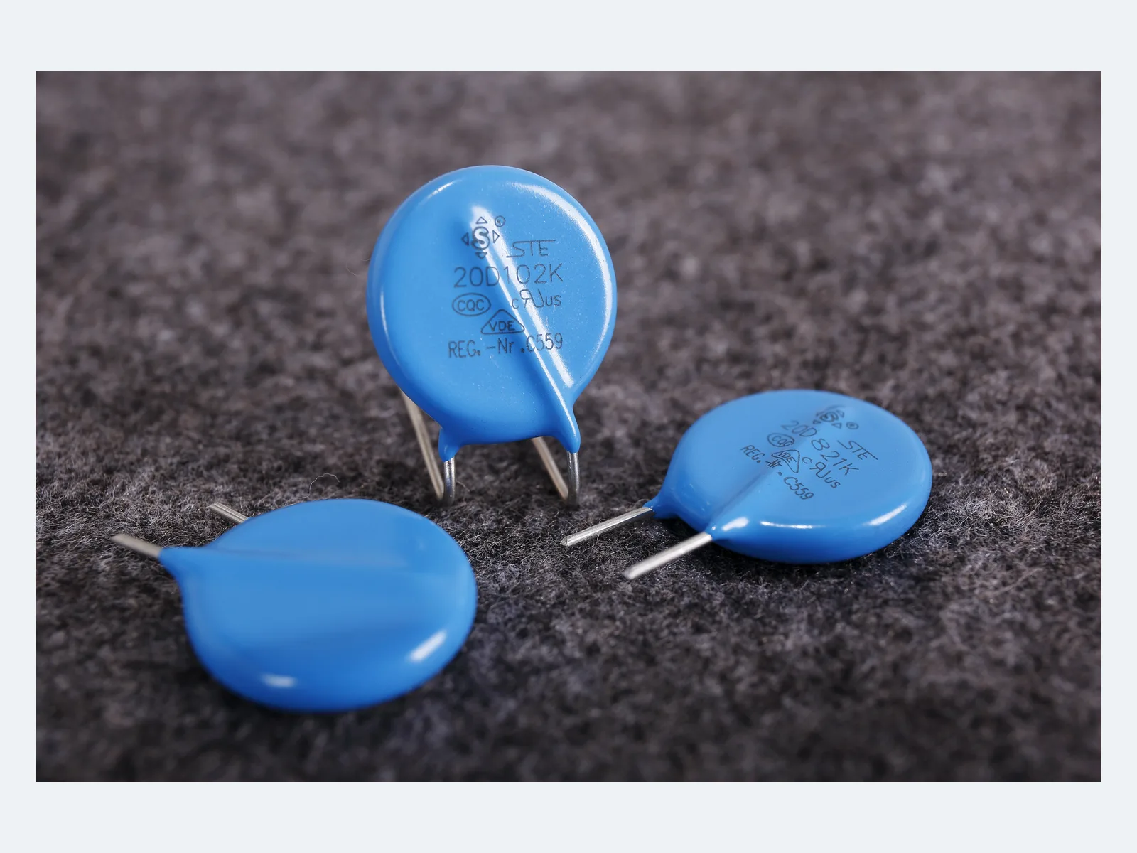
High-energy radial-leaded zinc-oxide disc varistors, 05D–25D; varistor voltage 18–1,200 V, max. peak current 18 kA (8/20 µs), max. energy 750 J (10/1000 µs).
Showing 16 of 1,259 part numbers
| Datasheet | |||||||||||
|---|---|---|---|---|---|---|---|---|---|---|---|
| STE05D180K1BN0FZB0R0 | Z | 5 | 18 | 11 | 14 | 40 | 1 | 250 | 0.6 | 0.01 | |
| STE05D220K1BN0FZB0R0 | Z | 5 | 22 | 14 | 18 | 48 | 1 | 250 | 0.7 | 0.01 | |
| STE05D270K1BN0FZB0R0 | Z | 5 | 27 | 17 | 22 | 60 | 1 | 250 | 0.9 | 0.01 | |
| STE05D330K1BN0FZB0R0 | Z | 5 | 33 | 20 | 26 | 73 | 1 | 250 | 1.1 | 0.01 | |
| STE05D390K1BN0FZB0R0 | Z | 5 | 39 | 25 | 31 | 80 | 1 | 250 | 1.2 | 0.01 | |
| STE05D470K1BN0FZB0R0 | Z | 5 | 47 | 30 | 38 | 104 | 1 | 250 | 1.5 | 0.01 | |
| STE05D560K1BN0FZB0R0 | Z | 5 | 56 | 35 | 45 | 123 | 1 | 250 | 1.8 | 0.01 | |
| STE05D680K1BN0FZB0R0 | Z | 5 | 68 | 40 | 56 | 145 | 1 | 250 | 2.2 | 0.01 | |
| STE05D820K1BN0FZB0R0 | Z | 5 | 82 | 50 | 65 | 150 | 5 | 800 | 4 | 0.1 | |
| STE05D101K1BN0FZB0R0 | Z | 5 | 100 | 60 | 85 | 175 | 5 | 800 | 4.1 | 0.1 | |
| STE05D121K1BN0FZB0R0 | Z | 5 | 120 | 75 | 100 | 210 | 5 | 800 | 5.5 | 0.1 | |
| STE05D151K1BN0FZB0R0 | Z | 5 | 150 | 95 | 125 | 260 | 5 | 800 | 6.5 | 0.1 | |
| STE05D181K1BN0FZB0R0 | Z | 5 | 180 | 115 | 150 | 320 | 5 | 800 | 7.5 | 0.1 | |
| STE05D201K1BN0FZB0R0 | Z | 5 | 200 | 130 | 170 | 355 | 5 | 800 | 8.5 | 0.1 | |
| STE05D221K1BN0FZB0R0 | Z | 5 | 220 | 140 | 180 | 380 | 5 | 800 | 9 | 0.1 | |
| STE05D221K3BA5FZB0R0 | Z | 5 | 220 | 140 | 180 | 380 | 5 | 800 | 9 | 0.1 |
— = not specified
Need a value that is not listed? Send us your specification.
Datasheets, technical documents and approval certificates for this series. English editions of documents marked “Chinese” are available on request.
High-energy radial-leaded metal-oxide varistors with epoxy-coated zinc-oxide discs, rated for higher one-pulse peak current and energy than the S series. Disc sizes 05D to 25D, nominal varistor voltage 18–1,200 V, max. continuous voltage 11–750 VAC / 14–990 VDC. Max. peak current 250–18,000 A (8/20 µs, one pulse), max. energy 0.6–750 J (10/1000 µs).
| Function | High-energy radial-leaded zinc-oxide varistor for transient voltage clamping; include finite pulse life and degradation in the protection design |
|---|---|
| Construction | Epoxy-coated zinc-oxide disc with radial leads |
| Reference standards | GB/T 10193 · GB/T 10194 · GB 8898-2011 · GB 4943.1-2011 · UL 1449 · IEC 61051 · IEC 60950-1:2013 |
| Disc sizes | 05D · 07D · 10D · 14D · 20D · 25D |
| Nominal varistor voltage | 18–680 V (05D) · 18–820 V (07D) · 18–1,100 V (10D, 14D, 20D) · 180–1,200 V (25D) |
| Max. continuous voltage | 11–750 VAC · 14–990 VDC; per disc size and voltage code |
| Varistor voltage measured at | 0.1 mA (05D) · 1 mA (07D, 10D, 14D, 20D, 25D) |
| Varistor-voltage tolerance | K = ±10%. Min./max. limits per part number in the datasheet. |
| Max. clamping voltage | Specified per part number at test current IP; IP up to 100 A for high-voltage 20D and 25D types. Compare only at the same current and waveform. |
| Max. peak current, 8/20 µs, one pulse | 250–18,000 A; per disc size and voltage code |
| Max. peak current, 8/20 µs, two pulses | 100–6,500 A (05D–20D) · 25D on request |
| Max. energy absorption, 10/1000 µs | 0.6–750 J; per part number |
| Rated power | 0.01–1.0 W (05D–20D) · 25D on request |
| Capacitance (typical) | 38–28,500 pF (05D–20D) · 600–3,900 pF (25D) · at 1 kHz |
| Z vs. S series | Higher one-pulse peak current and energy ratings than the S series |
| Operating temperature | −40 °C to +105 °C (05D, 07D) · −40 °C to +125 °C (10D, 14D, 20D, 25D). Temperature grade by part number: see datasheet. |
| Dimensions, 05D | D max. 7.5 mm · T max. 3.5–5.5 mm · lead pitch F 5.0 ±0.5 mm · lead Ø d 0.5 ±0.05 mm |
| Dimensions, 07D | D max. 9.0 mm · T max. 3.5–5.5 mm · lead pitch F 5.0 ±0.5 mm · lead Ø d 0.5 ±0.05 mm |
| Dimensions, 10D | D max. 12.5 mm · T max. 4.0–7.5 mm · lead pitch F 7.5 ±0.5 mm · lead Ø d 0.7 ±0.05 mm |
| Dimensions, 14D | D max. 16.0 mm · T max. 4.0–7.5 mm · lead pitch F 7.5 ±0.5 mm · lead Ø d 0.7 ±0.05 mm |
| Dimensions, 20D | D max. 23 mm (18–68 V), 21 mm (from 82 V) · T 4.0–8.0 mm · lead pitch F 10 ±0.5 mm · lead Ø d 1.0 mm straight / 0.8 mm bent, ±0.05 mm |
| Dimensions, 25D | D max. 28.5 mm · T max. 4.7–10.5 mm · lead pitch F 12.7 ±0.5 mm · lead Ø d 1.0 ±0.05 mm |
| Lead forms | Long straight · single outward bend · short straight · front/rear raised; 25D: straight leads, 12.7 mm pitch |
| Lead length | Long straight ≥16 mm; short or bent 2.5–<6 mm ±0.5 mm or 6–10 mm ±1.0 mm. Coating run-down and bend height depend on the lead form. |
| Packing | Bulk or taped; taping for 5, 7.5 and 10 mm lead pitch · 25D packing on request |
| Hand soldering and rework | 350 °C max. · 3 s max. · solder point at least 2 mm from the coating |
| End-of-life protection | Sustained abnormal voltage can raise leakage current and heat the varistor. Coordinate a fuse or thermal disconnector. |
| SPD classification | Component ratings alone do not establish an IEC 61643 / UL 1449 SPD class, nominal or max. discharge current, voltage protection level or SCCR. |
| Storage | ≤35 °C · ≤70% RH · no corrosive gas or direct sunlight · 12 months max. |
| Further data | On request: derating of peak current, energy, continuous voltage and leakage current versus temperature · wave-soldering, preheat, cleaning and conformal-coating conditions · max. standby leakage, leakage versus temperature and post-surge leakage limits · V-I curves, dynamic resistance and temperature coefficients of clamping and varistor voltage · peak-current and energy derating versus pulse count, pulse width and interval · TOV and failure-mode data · endurance, damp-heat, thermal-cycling, vibration, lead-strength and solderability results |
Ranges by dielectric, package and lead style within this series.
| Variant | Body dimensions | Varistor voltage / max. continuous voltage | Peak current (8/20 µs, one pulse) / energy (10/1000 µs) / rated power | Lead / land pattern | Notes |
|---|---|---|---|---|---|
| 05D-Z | D max. 7.5 mm · T max. 3.5–5.5 mm | 18–680 V · 11–420 VAC · 14–560 VDC | 250–800 A · 0.6–29.1 J · 0.01–0.1 W | F 5.0 ±0.5 mm · d 0.5 ±0.05 mm | Smallest Z disc. Operating temperature up to +105 °C. |
| 07D-Z | D max. 9.0 mm · T max. 3.5–5.5 mm | 18–820 V · 11–510 VAC · 14–670 VDC | 500–1,750 A · 2–73 J · 0.02–0.25 W | F 5.0 ±0.5 mm · d 0.5 ±0.05 mm | Compact size. Operating temperature up to +105 °C. |
| 10D-Z | D max. 12.5 mm · T max. 4.0–7.5 mm | 18–1,100 V · 11–680 VAC · 14–895 VDC | 1,000–3,500 A · 3–155 J · 0.05–0.4 W | F 7.5 ±0.5 mm · d 0.7 ±0.05 mm | Smallest disc rated to +125 °C. |
| 14D-Z | D max. 16.0 mm · T max. 4.0–7.5 mm | 18–1,100 V · 11–680 VAC · 14–895 VDC | 2,000–6,000 A · 7–360 J · 0.1–0.6 W | F 7.5 ±0.5 mm · d 0.7 ±0.05 mm | Mid- to high-energy industrial inputs. Check the number of events and fail-safe protection. |
| 20D-Z | D max. 23 mm (18–68 V), 21 mm (from 82 V) · T max. 4.0–8.0 mm | 18–1,100 V · 11–680 VAC · 14–895 VDC | 3,000–10,000 A · 13–720 J · 0.2–1.0 W | F 10 ±0.5 mm · d 1.0 mm straight / 0.8 mm bent, ±0.05 mm | High-energy radial size. Peak current and temperature grade vary by part number; check mechanical support on the board. |
| 25D-Z | D max. 28.5 mm · T max. 4.7–10.5 mm | 180–1,200 V · 115–750 VAC · 150–990 VDC | 18,000 A · 180–750 J | F 12.7 ±0.5 mm · d 1.0 ±0.05 mm | Highest energy in the series, for severe surges. Coordinate pulse life, fuse or thermal protection and board support. |
Use the Z series where the S series lacks surge margin. Coordinate max. continuous and temporary voltage, clamping at the actual current, waveform, energy, number of events, ambient temperature, degradation and fail-safe disconnection. Then choose the smallest disc that meets the complete mission profile.
State nominal and max. AC or DC voltage, frequency, harmonics, tolerance, grounding and every TOV duration. Select from the max. continuous VAC/VDC, not from the nominal varistor voltage.
State open-circuit voltage, short-circuit current, source impedance, current waveform (8/20 µs or other), voltage waveform (1.2/50 µs or other), polarity, interval and lifetime event count. Do not design to the one-pulse rating.
Use the clamping voltage at its stated test current together with the complete V-I curve and its temperature tolerance, include lead and PCB inductance and check the downstream absolute maximum ratings at the actual current.
Ratings are given as 10/1000 µs energy and one- and two-pulse 8/20 µs peak current. Derate for waveform, pulse count, interval, temperature and accumulated degradation.
Specify disc size, voltage code, temperature grade, lead form, packing, drawing and approval scope for each part number. Coordinate fusing or thermal disconnection, fire enclosure, soldering process and an inspection or replacement policy.
Approval coverage depends on disc size, voltage value, type suffix and construction.
| Agency | Standard | Certificate | Scope |
|---|---|---|---|
 CQC CQC | GB/T 10193 · GB/T 10194 · GB 8898 · GB 4943.1 | 05D 19001213185 · 07D 19001213190 · 10D 19001213188 · 14D 19001213191 · 20D 19001213192 · 25D 21001289415 | Covers defined voltage ranges per disc size. The 25D certificate covers voltage codes 181K–122K and is valid to 31 Oct 2027, subject to surveillance. |
 UL / cUL UL / cUL | UL 1449 | E330837 | Recognized component; covers 5D–25D and selected high-temperature types. Coverage varies by Z suffix, voltage, coating, lead style and factory. |
 VDE VDE | IEC 61051 · IEC 60950-1:2013 | 40023049 | Covers specific voltage values per disc size, including most 25D values; not all values are covered. |
Each certificate covers the types and ratings listed on it.
Peak current and energy ratings are one- or two-pulse limits, not a repetitive operating point. Derate for waveform, number of events, interval, temperature and previous stress.
18–1,200 V is the nominal varistor-voltage range, not the operating voltage. Select from the lower max. continuous AC/DC rating after including line tolerance, harmonics, grounding and TOV.
The clamping voltage at one test current does not describe every surge. Use the V-I curve and temperature tolerance from STE, include PCB and lead inductance, and measure the residual voltage at the protected load.
Sustained abnormal voltage can raise leakage current and heat the varistor. Coordinate a fuse or thermal protector, fire enclosure, SCCR and available fault current, and safe indication or replacement. A larger disc does not remove this requirement.
25D types start at 180 V nominal varistor voltage and use 12.7 mm lead pitch. Two-pulse current, rated power, drawing, packing and mounting data on request.
Example ordering code. Not every combination is available.
STE · 20 · D · 471 · K · 1 · D · N0 · F · Z · B · 0 · R · 0
| Code | Meaning |
|---|---|
| STE | STE prefix |
| 20 | Disc diameter: 20 = 20 mm; 05, 07, 10, 14, 25 for the other sizes |
| D | Disc shape |
| 471 | Nominal varistor voltage: 471 = 470 V; 220 = 22 V, 122 = 1,200 V |
| K | Varistor-voltage tolerance: K = ±10% |
| 1 | Lead form: 1 = long straight; 2 = single outward bend, 3 = short straight, 8 = front/rear raised |
| D | Lead pitch: D = 10.0 mm; B = 5.0 mm, E = 7.5 mm; 12.7 mm (25D) code on request |
| N0 | Lead length or taped height; the code depends on bulk or taped packing (code list on request) |
| F | Lead material: F = tin-plated copper-clad steel; C = copper wire |
| Z | Varistor type: Z = high-energy series |
| B | Packing: B = bulk; T = taped |
| 0 | Factory code, assigned by STE |
| R | Environmental code: R = RoHS; F = RoHS and halogen-free |
| 0 | Factory code, assigned by STE |