Q

Q Series 6kV/3kA Radial-Leaded Metal-Oxide Varistors

Nominal varistor voltage82–1,100 V
Max. peak current (8/20 µs)3,500–10,000 A
Surge designation6 kV / 3 kA
Max. continuous voltage50–680 VAC / 65–895 VDC
Max. energy (10/1000 µs)30–720 J
Operating temperature−40 °C to +125 °C

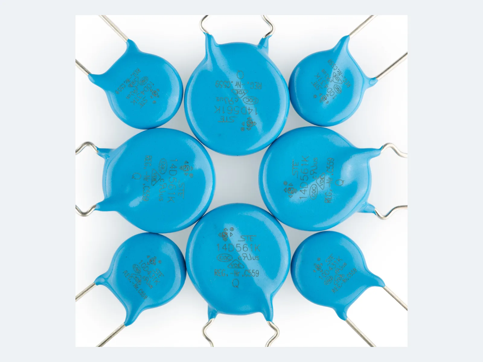
Surge-type radial-leaded zinc-oxide varistors designated 6 kV / 3 kA, 10D–20D; varistor voltage 82–1,100 V, max. peak current 10 kA (8/20 µs).

Series product photograph

Part numbers

656

Showing 25 of 656 part numbers

STE10D391K1EN0FQB0R010390250320650253,500820.4
STE10D391K1EN0FQB1R010390250320650253,500820.4
STE10D391K1EQ0FQT0R010390250320650253,500820.4
STE10D391K3EA5FQB0R010390250320650253,500820.4
STE10D431K1EN0FQB0R010430275350710253,500930.4
STE10D431K1EN0FQB1R010430275350710253,500930.4
STE10D431K3EA5FQB0R010430275350710253,500930.4
STE10D471K1DQ0FQT0RP10470300385775253,500990.4
STE10D471K1EN0FQB0M010470300385775253,500990.4
STE10D471K1EN0FQB0R010470300385775253,500990.4
STE10D471K1EN0FQB1R010470300385775253,500990.4
STE10D471K1EN0FQB1R210470300385775253,500990.4
STE10D471K1EN0FQBDRA10470300385775253,500990.4
STE10D471K1EQ0FQT0R010470300385775253,500990.4
STE10D471K1EQ0FQT0RP10470300385775253,500990.4
STE10D471K2EA4FQB0R010470300385775253,500990.4
STE10D471K2EA6FQB0R010470300385775253,500990.4
STE10D471K2EF0FQB0R010470300385775253,500990.4
STE10D471K2EP0FQT0F010470300385775253,500990.4
STE10D471K2EP0FQT0R010470300385775253,500990.4
STE10D471K2EP0FQT0RP10470300385775253,500990.4
STE10D471K3EA0FQB0R010470300385775253,500990.4
STE10D471K3EA0FQB0RH10470300385775253,500990.4
STE10D471K3EA2FQB0R010470300385775253,500990.4
STE10D471K3EA3FQB0R010470300385775253,500990.4

— = not specified

Need a value that is not listed? Send us your specification.

Datasheets & approval documents

Datasheets, technical documents and approval certificates for this series. English editions of documents marked “Chinese” are available on request.

Need a document not listed here? Ask us

Engineering details

Overview

Surge-type (Q) radial-leaded metal-oxide varistors with zinc-oxide discs, designated 6 kV / 3 kA. Disc sizes 10D, 14D and 20D, nominal varistor voltage 82–1,100 V, max. continuous voltage 50–680 VAC / 65–895 VDC. Max. peak current 3,500–10,000 A (8/20 µs, one pulse), max. energy 30–720 J (10/1000 µs). Operating temperature −40 °C to +125 °C.

Series features

  • Three disc sizes, 10D, 14D and 20D; nominal varistor voltage 82–1,100 V
  • Max. continuous voltage 50–680 VAC and 65–895 VDC
  • Max. peak current, 8/20 µs, one / two pulses: 3.5 / 2.5 kA (10D), 6 / 4.5 kA (14D), 10 / 6.5 kA (20D)
  • Operating temperature −40 °C to +125 °C
Specifications
FunctionRadial-leaded zinc-oxide varistor for transient overvoltage clamping. The varistor alone is not an equipment immunity result, an SPD, a fuse or a thermal disconnector.
Type designationQ = surge type, designated 6 kV / 3 kA
Nominal varistor voltage82–1,100 V at 1 mA; 10D from 390 V, 14D and 20D from 82 V
Max. continuous AC voltage250–680 VAC (10D) · 50–680 VAC (14D, 20D)
Max. continuous DC voltage320–895 VDC (10D) · 65–895 VDC (14D, 20D)
Max. peak current 8/20 µs, 10D3,500 A one pulse · 2,500 A two pulses; clamping voltage measured at IP = 25 A
Max. energy 10/1000 µs, 10D82–180 J (390–1,100 V)
Rated power / capacitance, 10D0.4 W · 90–300 pF at 1 kHz (reference)
Max. peak current 8/20 µs, 14D6,000 A one pulse · 4,500 A two pulses; clamping voltage measured at IP = 50 A
Max. energy 10/1000 µs, 14D30–365 J (82–1,100 V)
Rated power / capacitance, 14D0.6 W · 180–3,700 pF at 1 kHz (reference)
Max. peak current 8/20 µs, 20D10,000 A one pulse · 6,500 A two pulses; clamping voltage measured at IP = 100 A
Max. energy 10/1000 µs, 20D100–720 J (82–1,100 V)
Rated power / capacitance, 20D1.0 W · 360–7,500 pF at 1 kHz (reference)
Max. clamping voltageSpecified per part number at one test current IP per disc size (25 / 50 / 100 A). Compare only at the same current and waveform.
Pulse ratings and 6 kV / 3 kAOne- and two-pulse 8/20 µs ratings do not define a 6 kV / 3 kA immunity test sequence.
Q vs. Z series, electricalContinuous voltage, varistor voltage, clamping voltage, peak current, rated power and capacitance equal the Z series at the same disc size and voltage; only the 10/1000 µs energy differs.
Q vs. Z series, energyEqual or higher 10/1000 µs energy: 10D +12–36 J (about 16–34%); most 14D values up to +16 J; 20D equal
Q vs. Z series, dimensions10D: D max. +1.0 mm, T max. +0.5–2.0 mm; some 14D and 20D values: T max. +0.5–2.0 mm
Operating temperature−40 °C to +125 °C
Dimensions, 10DD max. 13.5 mm · T max. 5.5–9.5 mm · lead pitch F 7.5 ±0.5 mm · lead Ø d 0.7 ±0.05 mm
Dimensions, 14DD max. 16.0 mm · T max. 4.0–9.5 mm · lead pitch F 7.5 ±0.5 mm · lead Ø d 0.7 ±0.05 mm
Dimensions, 20DD max. 21.0 mm · T max. 4.0–9.5 mm · lead pitch F 10.0 ±0.5 mm · lead Ø d 1.0 mm straight / 0.8 mm bent, ±0.05 mm
Lead formsLong straight · single outward bend · short straight · front/rear raised
Lead lengthLong straight ≥16 mm; short or bent 2.5–<6 mm ±0.5 mm or 6–10 mm ±1.0 mm. Coating run-down, bend height and taped H0 depend on the lead form.
PackingBulk or taped; taping for 7.5 and 10 mm lead pitch, component pitch 25.4 mm
Hand soldering and rework350 °C max. · 3 s max. · solder point at least 2 mm from the coating
End-of-life protectionSustained abnormal voltage can raise leakage current and heat the varistor. Coordinate a fuse or thermal disconnector.
Further data on request6 kV / 3 kA test standard, waveform, generator impedance, coupling, polarity, phase angle, pulse count and interval, operating mode and acceptance criteria · pulse recovery and post-pulse limits of varistor voltage, clamping voltage and leakage · derating of continuous voltage, peak current, energy and leakage current up to +125 °C · max. standby and post-surge leakage current, V-I curves, dynamic resistance and temperature coefficients of clamping and varistor voltage · TOV and failure-mode data · 6 kV / 3 kA test reports, repetitive-pulse curves and endurance, damp-heat, thermal-cycling, vibration, lead-strength and solderability results
Variants

Ranges by dielectric, package and lead style within this series.

VariantBody dimensionsVaristor voltage / max. continuous voltagePeak current (8/20 µs, one / two pulses) / energy (10/1000 µs) / rated powerLead / land patternNotes
10D-QD max. 13.5 mm · T max. 5.5–9.5 mm390–1,100 V · 250–680 VAC · 320–895 VDC3,500 / 2,500 A · 82–180 J · 0.4 WF 7.5 ±0.5 mm · d 0.7 ±0.05 mmCompact Q size; 10/1000 µs energy higher than the 10D Z type at every voltage.
14D-QD max. 16.0 mm · T max. 4.0–9.5 mm82–1,100 V · 50–680 VAC · 65–895 VDC6,000 / 4,500 A · 30–365 J · 0.6 WF 7.5 ±0.5 mm · d 0.7 ±0.05 mmWidest voltage range in the series. Energy equal to or higher than the 14D Z type.
20D-QD max. 21.0 mm · T max. 4.0–9.5 mm82–1,100 V · 50–680 VAC · 65–895 VDC10,000 / 6,500 A · 100–720 J · 1.0 WF 10 ±0.5 mm · d 1.0 mm straight / 0.8 mm bent, ±0.05 mmHighest peak current and energy in the series. Electrical ratings equal the 20D Z type; select Q for its construction and a system surge test.
Selection guide

Treat 6 kV / 3 kA as an equipment surge requirement and define the complete generator and pass criteria. Then select max. continuous voltage, clamping at the protected load, disc size and energy, pulse sequence, temperature, TOV and fail-safe disconnection.

  1. Define the 6 kV / 3 kA test method

    Name the governing standard and edition, 1.2/50 µs and 8/20 µs tolerances, generator impedance (2 Ω or other), coupling network, polarity, phase angle, pulse count and interval, operating mode, number of specimens and acceptance criteria.

  2. Select max. continuous VAC/VDC first

    Include line tolerance, frequency, harmonics, grounding and every TOV duration. Do not use the nominal varistor voltage as the continuous rating.

  3. Coordinate clamping with protected-load withstand

    Use the V-I curve and temperature tolerance (on request). Include generator voltage collapse during clamping and lead/PCB inductive overshoot, and measure the residual voltage at the actual protected load.

  4. Check energy, pulse count and temperature margin

    Check derating versus pulse count, interval, waveform duration and temperature up to +125 °C, and the post-stress limits for varistor voltage, clamping voltage and leakage (data on request).

  5. Specify part number, approvals and safe end of life

    Fix disc size, voltage, construction, drawing, marking, lead form, packing, temperature grade and approvals with the exact part number. Coordinate fuse or thermal disconnection, enclosure, soldering and inspection or replacement.

Approvals & reliability

Approvals & qualifications

Approval coverage depends on voltage value, construction, temperature grade, lead form and factory. The approvals below are component approvals, not an equipment-level 6 kV / 3 kA test report. Certificate copies on request.

AgencyStandardCertificateScope
CQC certification markCQCGB/T 10193 · GB/T 10194 · GB 8898 · GB 4943.110D 19001213188 · 14D 19001213191 · 20D 19001213192Covers defined voltage values, constructions and temperature grades.
UL certification markUL / cULUL 1449E330837Recognized component. Component recognition alone does not establish IEC 61000-4-5 immunity, IEC 62368-1 Annex G compliance or an SPD classification.
VDE certification markVDEIEC 61051 · IEC 60950-1:201340023049Covers specific voltage values. Model list and constructions on request.

Each certificate covers the types and ratings listed on it.

Design notes

A 6 kV / 3 kA designation is not a test plan

Define the waveform tolerances, source impedance, coupling, polarity, phase angle, pulse count, interval, operating mode and pass criteria. Equipment immunity cannot be inferred from the ratings of one varistor.

Separate limit, nominal and repetitive current

The one-pulse 8/20 µs peak current is a limit value, not a repetitive rating. Distinguish it from repeated surge current, the 6 kV / 3 kA test sequence and the lifetime margin.

Q and Z ratings differ only in energy

At equal disc size and voltage, Q and Z share all ratings except the 10/1000 µs energy, which is equal or higher for Q. Select Q for its construction and a validated system surge test, not for the suffix alone.

Coordinate TOV, fuse and thermal disconnection

Sustained abnormal voltage can raise leakage current and heat the varistor, even after a passed surge test. Coordinate available fault current, fuse or thermal protector, enclosure and safe indication or replacement.

Part numbering

Example ordering code. Not every combination is available.

STE · 10 · D · 471 · K · 1 · E · N0 · F · Q · B · 0 · R · 0

CodeMeaning
STESTE prefix
10Disc diameter: 10 = 10 mm; 14, 20 for the other sizes
DDisc shape
471Nominal varistor voltage: 471 = 470 V; range 820 (82 V) to 112 (1,100 V); 10D from 391 (390 V)
KVaristor-voltage tolerance: K = ±10%
1Lead form: 1 = long straight; 2 = single outward bend, 3 = short straight, 8 = front/rear raised
ELead pitch: E = 7.5 mm; D = 10.0 mm (20D)
N0Lead length or taped height; the code depends on bulk or taped packing (code table on request)
FLead material: F = tin-plated copper-clad steel; C = copper wire
QVaristor type: Q = surge type, designated 6 kV / 3 kA
BPacking: B = bulk; T = taped
0Factory code, assigned by STE
REnvironmental code: R = RoHS; F = RoHS and halogen-free
0Factory code, assigned by STE