
Select from max. continuous voltage
Include tolerance, charging behavior, jump start, reverse voltage and every TOV duration. Nominal varistor voltage is not an operating rating.
| Automotive qualification | AEC-Q200 qualified part numbers available |
|---|---|
| Nominal varistor voltage | 82–1,000 V |
| Max. peak current (8/20 µs) | 3,500–10,000 A |
| Max. continuous voltage | 50–625 VAC / 65–825 VDC |
| Max. energy (10/1000 µs) | 29.4–280 J |
| Operating temperature | −40 °C to +125 °C |



Radial-leaded zinc-oxide varistors, 10D–20D, for automotive electronics, with AEC-Q200 qualified part numbers available; varistor voltage 82–1,000 V, max. peak current 10 kA (8/20 µs).
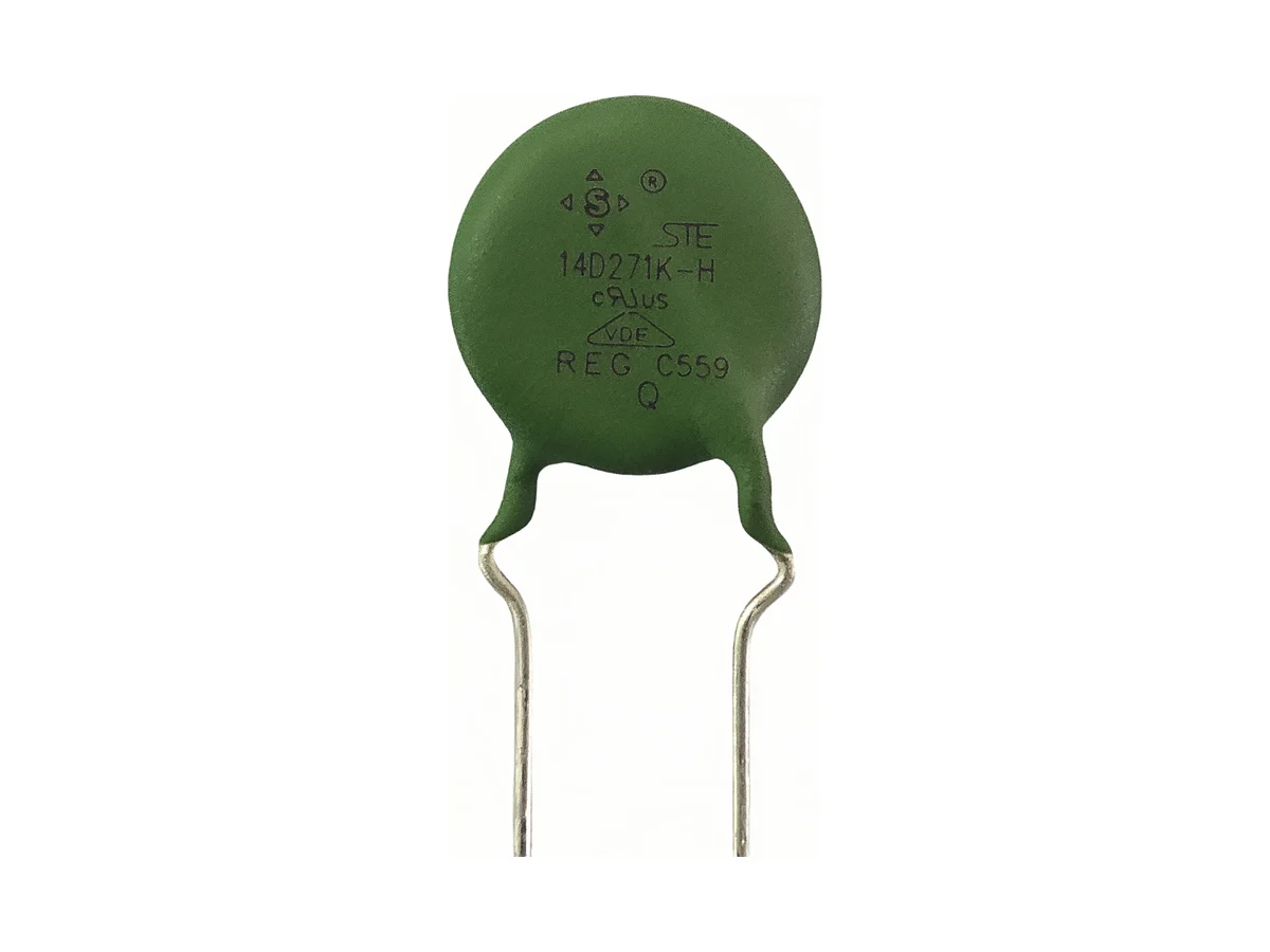
Showing 21 of 21 part numbers
| STE10D621K2EB5FQB0Q2 | 10 | 620 | 385 | 505 | 1,025 | 25 | 3,500 | 102.2 | 0.4 | 7.5 |
|---|---|---|---|---|---|---|---|---|---|---|
| STE10D621K2EP0FQT0Q2 | 10 | 620 | 385 | 505 | 1,025 | 25 | 3,500 | 102.2 | 0.4 | 7.5 |
| STE10D681K1EN0FQB0Q0 | 10 | 680 | 420 | 560 | 1,120 | 25 | 3,500 | 102.2 | 0.4 | 7.5 |
| STE10D911K2EP0FQT0Q0 | 10 | 910 | 550 | 745 | 1,500 | 25 | 3,500 | 133 | 0.4 | 7.5 |
| STE14D471K1EN0FQB0Q0 | 14 | 470 | 300 | 385 | 775 | 50 | 6,000 | 149.8 | 0.6 | 7.5 |
| STE14D511K2EP0FQT0Q2 | 14 | 510 | 320 | 415 | 845 | 50 | 6,000 | 149.8 | 0.6 | 7.5 |
| STE14D621K1EN0FQB0Q0 | 14 | 620 | 385 | 505 | 1,025 | 50 | 6,000 | 168 | 0.6 | 7.5 |
| STE14D621K4EP0FQT0QK | 14 | 620 | 385 | 505 | 1,025 | 50 | 6,000 | 168 | 0.6 | 7.5 |
| STE14D621K8EB5FQB0Q0 | 14 | 620 | 385 | 505 | 1,025 | 50 | 6,000 | 168 | 0.6 | 7.5 |
| STE14D621K8EP0FQT0Q0 | 14 | 620 | 385 | 505 | 1,025 | 50 | 6,000 | 168 | 0.6 | 7.5 |
| STE14D821K2EP0FQT0QA | 14 | 820 | 510 | 670 | 1,355 | 50 | 6,000 | 203 | 0.6 | 7.5 |
| STE14D821K8EB5FQB0Q2 | 14 | 820 | 510 | 670 | 1,355 | 50 | 6,000 | 203 | 0.6 | 7.5 |
| STE14D821K8EP0FQT0Q2 | 14 | 820 | 510 | 670 | 1,355 | 50 | 6,000 | 203 | 0.6 | 7.5 |
| STE20D391K1DN0FQBDQK | 20 | 390 | 250 | 320 | 650 | 100 | 10,000 | 182 | 1 | 10 |
| STE20D391K2DP0FQTDQA | 20 | 390 | 250 | 320 | 650 | 100 | 10,000 | 182 | 1 | 10 |
| STE20D511K8DB5FQBDQ0 | 20 | 510 | 320 | 415 | 845 | 100 | 10,000 | 210 | 1 | 10 |
| STE20D511K8DP0FQTDQ0 | 20 | 510 | 320 | 415 | 845 | 100 | 10,000 | 210 | 1 | 10 |
| STE14D561K1EN0FQB0TA | — | — | — | — | — | — | — | — | — | — |
| STE20D621K8DB5FZBDQ2 | — | — | — | — | — | — | — | — | — | — |
| STE20D621K8DP0FZTDQ0 | — | — | — | — | — | — | — | — | — | — |
| STE20D621K8DP0FZTDQ2 | — | — | — | — | — | — | — | — | — | — |
— = not specified
Need a value that is not listed? Send us your specification.
Datasheets, technical documents and approval certificates for this series. English editions of documents marked “Chinese” are available on request.
Radial-leaded metal-oxide varistors with zinc-oxide discs for automotive electronics; AEC-Q200 qualified part numbers available. Disc sizes 10D, 14D and 20D, nominal varistor voltage 82–1,000 V, max. continuous voltage 50–625 VAC / 65–825 VDC. Max. peak current 3,500–10,000 A (8/20 µs, one pulse). Operating temperature −40 °C to +125 °C.
| Function | Radial-leaded zinc-oxide varistor for bidirectional transient clamping. The varistor alone is not an automotive immunity result, a fuse, a thermal disconnector or an SPD. |
|---|---|
| Series | Automotive Q-type varistors in 10D, 14D and 20D. Ratings are per disc size and voltage; 6 kV / 3 kA test conditions on request. |
| Construction | Epoxy-coated zinc-oxide disc with radial leads |
| Coating flammability | UL 94 V-0 epoxy, yellow coating |
| Automotive qualification | AEC-Q200 qualified part numbers available; qualification report, temperature grade and production site on request |
| Max. continuous AC voltage | 250–625 VAC (10D) · 50–625 VAC (14D, 20D); per voltage code |
| Max. continuous DC voltage | 320–825 VDC (10D) · 65–825 VDC (14D, 20D); per voltage code |
| Nominal varistor voltage | 82–1,000 V at 1 mA (10D: 390–1,000 V) · tolerance K = ±10%; limits per part number |
| Max. clamping voltage | Specified at IP = 25 A (10D), 50 A (14D), 100 A (20D) |
| Max. peak current 8/20 µs, 10D | 3,500 A one pulse · 2,500 A two pulses |
| Energy / power / capacitance, 10D | 68.2–133 J (10/1000 µs) · 0.4 W · 110–300 pF at 1 kHz (reference) |
| Max. peak current 8/20 µs, 14D | 6,000 A one pulse · 4,500 A two pulses |
| Energy / power / capacitance, 14D | 29.4–217 J (10/1000 µs) · 0.6 W · 230–3,700 pF at 1 kHz (reference) |
| Max. peak current 8/20 µs, 20D | 10,000 A one pulse · 6,500 A two pulses |
| Energy / power / capacitance, 20D | 37.8–280 J (10/1000 µs) · 1.0 W · 450–7,500 pF at 1 kHz (reference) |
| Waveform ratings | 8/20 µs current and 10/1000 µs energy are separate tests. Neither defines an ISO 7637-2 or ISO 16750-2 load-dump, jump-start or repetitive-pulse limit. |
| Operating temperature | −40 °C to +125 °C |
| Storage | ≤35 °C · ≤70% RH · no corrosive gas or direct sunlight · 12 months max. |
| Dimensions, 10D | D max. 14.0 mm · T max. 6.0–9.5 mm · lead pitch F 7.5 ±0.5 mm · lead Ø d 0.7 ±0.05 mm |
| Dimensions, 14D | D max. 16.5 mm · T max. 4.5–9.5 mm · lead pitch F 7.5 ±0.5 mm · lead Ø d 0.7 ±0.05 mm |
| Dimensions, 20D | D max. 21.0 mm · T max. 4.5–9.5 mm · lead pitch F 10 ±0.5 mm · lead Ø d 1.0 mm straight / 0.8 mm bent, ±0.05 mm |
| Lead forms | Long straight · short straight · single outward bend · single inward bend (code on request) · front/rear raised |
| Lead length | Long straight ≥16 mm; short or bent 2.5–<6 mm ±0.5 mm or 6–10 mm ±1.0 mm. Coating run-down and bend height depend on the lead form. |
| Taping | Lead pitch 7.5 / 10 mm · component pitch 25.4 ±1.0 mm · carrier width 18 mm · H0 and lead length depend on the lead form |
| Hand soldering and rework | 350 °C max. · 3 s max. · solder joint at least 2 mm from the coating |
| End-of-life protection | Sustained abnormal voltage can raise leakage current and heat the varistor. Coordinate a fuse or thermal disconnector and flame containment. |
| Further data on request | V-I curves and production and temperature tolerance of clamping voltage · derating versus pulse count, interval and duty, and post-pulse limits · derating of continuous voltage, peak current, energy, rated power and leakage current up to +125 °C · max. standby current, post-surge leakage, drift of varistor and clamping voltage, and temperature coefficients · wave-soldering, preheat, cleaning and coating conditions · load dump and jump start: ISO pulse, source impedance, voltage–time profile, pulse count, polarity and pass criteria for the target rail · TOV and failure-mode data · PPAP scope, production traceability and change notification |
Ranges by dielectric, package and lead style within this series.
| Variant | Body dimensions | Varistor voltage / max. continuous voltage | Peak current (8/20 µs, one / two pulses) / energy (10/1000 µs) / rated power | Lead / land pattern | Notes |
|---|---|---|---|---|---|
| 10D-QA | D max. 14.0 mm · T max. 6.0–9.5 mm | 390–1,000 V · 250–625 VAC · 320–825 VDC | 3,500 / 2,500 A · 68.2–133 J · 0.4 W | F 7.5 ±0.5 mm · d 0.7 ±0.05 mm | Compact size for higher voltages. |
| 14D-QA | D max. 16.5 mm · T max. 4.5–9.5 mm | 82–1,000 V · 50–625 VAC · 65–825 VDC | 6,000 / 4,500 A · 29.4–217 J · 0.6 W | F 7.5 ±0.5 mm · d 0.7 ±0.05 mm | Mid-size disc with the full voltage range, 82–1,000 V. |
| 20D-QA | D max. 21.0 mm · T max. 4.5–9.5 mm | 82–1,000 V · 50–625 VAC · 65–825 VDC | 10,000 / 6,500 A · 37.8–280 J · 1.0 W | F 10 ±0.5 mm · d 1.0 mm straight / 0.8 mm bent, ±0.05 mm | Highest peak current and energy in the series. |
Start from the vehicle transient and the continuous and temporary overvoltage, not from disc size or nominal varistor voltage. Then coordinate residual voltage, pulse energy and count, derating to +125 °C, leakage drift, AEC-Q200 scope and fail-safe protection.
State nominal and max. DC voltage, alternator or HV-bus behavior, reverse and jump start, load dump, inductive switching, ISO or OEM pulse, source impedance, polarity, count, interval, temperature and life.
Use the max. continuous VAC/VDC of the selected part number; temperature and TOV derating on request. Nominal varistor voltage is a measurement point, not a permissible operating voltage.
Use the clamping voltage at its test current with V-I and temperature data and PCB inductance. Check pulse-count, energy-duration, recovery and post-stress limits of leakage, varistor voltage and clamping voltage (data on request).
Request the AEC-Q200 report, qualified part numbers or family, temperature grade, production site, test groups, samples and lots, results and requalification history.
Fix coating, drawing, lead form, packing, process and approvals with the part number. Coordinate fuse or thermal disconnection, enclosure and service behavior.
AEC-Q200 qualification and the component approvals below are separate. AEC-Q200 report and approval coverage of individual part numbers on request.
| Agency | Standard | Certificate | Scope |
|---|---|---|---|
| CQC | GB/T 10193 · GB/T 10194 · GB 4943.1-2022 · IEC 61051-2 | 10D CQC19001213188 · 14D CQC19001213191 · 20D CQC19001213192 | Coverage varies with voltage value, coating, lead form, packing, type code and environmental code. |
| UL / cUL | UL 1449 | E330837 | Recognized component. Component recognition does not establish ISO or OEM automotive transient compliance or a protected-system result. |
| VDE | IEC 61051 · IEC 60950-1:2013 | 40023049 | Covers specific voltage values. Certificate appendix with coating, lead and packing coverage on request. |
Each certificate covers the types and ratings listed on it.
Include tolerance, charging behavior, jump start, reverse voltage and every TOV duration. Nominal varistor voltage is not an operating rating.
Name the ISO or OEM waveform, source impedance, polarity, count, interval and operating mode. An 8/20 µs peak current or 10/1000 µs energy rating does not replace load-dump validation.
Combine the V-I curve, temperature tolerance and interconnect inductance, then measure the peak at the protected node against semiconductor and insulation limits.
Coordinate pulse aging, leakage rise, TOV heating, fuse or thermal disconnection, flame containment and diagnostic or replacement behavior.
Specify the coating, lead form, lead length and packing in the part number. Validate soldering, cleaning, coating, vibration and the 12-month storage limit.
Example ordering code. Not every combination is available.
STE · 14 · D · 621 · K · 8 · E · B5 · F · Q · B · 0 · Q · 0
| Code | Meaning |
|---|---|
| STE | STE prefix |
| 14 | Disc diameter: 14 = 14 mm; 10, 20 for the other sizes |
| D | Disc shape |
| 621 | Nominal varistor voltage: 621 = 620 V; range 820 (82 V) to 102 (1,000 V); 10D from 391 (390 V) |
| K | Varistor-voltage tolerance: K = ±10% |
| 8 | Lead form: 8 = front/rear raised; 1 = long straight, 2 = single outward bend, 3 = short straight |
| E | Lead pitch: E = 7.5 mm; D = 10 mm (20D) |
| B5 | Lead length: B5 in this example; N0 and P0 depend on bulk or taped packing (code table on request) |
| F | Lead material: F = tin-plated copper-clad steel; C = copper wire |
| Q | Varistor type: Q = surge type |
| B | Packing: B = bulk; T = taped |
| 0 | Factory code, assigned by STE |
| Q | Environmental code: Q = automotive product; R = RoHS, F = RoHS and halogen-free |
| 0 | Factory code, assigned by STE |