
Not an X/Y safety capacitor
The series has no IEC 60384-14 safety class and no agency approval. For mains-connected positions, check whether the equipment standard requires a certified safety capacitor.
| Humidity type | 85 °C / 85% RH (double-85) |
|---|---|
| Rated voltage | 100 / 220 / 275 VAC |
| Capacitance | 0.01–4.7 µF |
| Tolerance | ±5% / ±10% |
| Lead spacing | 10–37.5 mm |
| Operating temperature | −40 °C to +105 °C |
Boxed metallized polypropylene film capacitors for high-frequency, AC, DC and pulse circuits; moisture-resistant double-85 type (85 °C / 85% RH). 100 / 220 / 275 VAC, 0.01–4.7 µF.
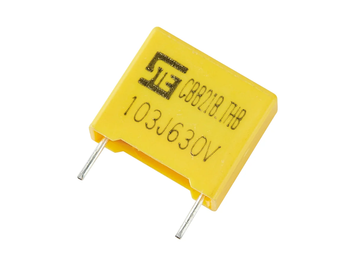
Showing 25 of 52 part numbers
| 2B1J304JJ144101085035FS8 |
|---|
| 2B1T684JQ5B0180190080FE8 |
| 2B1T684JQ5BO180145085FE8 |
| 2B2A254JJ735100120040FS8 |
| 2B2A304JJA25106101040FE8 |
| 2B2E104JJ140100090040FS8 |
| 2B2E254JDA38100110050FS8 |
| 2B2E254JJ140100120040FS8 |
| 2B2E254JJ170100110050FE8 |
| 2B2E254JJ1A5100110050FE8 |
| 2B2E254JJ1B0100160060FS8 |
| 2B2E254JJ5B0100110050FE8 |
| 2B2E254JJ723100110050FS8 |
| 2B2E254JJA16100110050FS8 |
| 2B2E254JJA27100110050FE8 |
| 2B2E254JJA27100110050FS8 |
| 2B2E254JJG27100110050FS8 |
| 2B2E474JJ140100160060FS8 |
| 2B2H105KQ135180210120ES8 |
| 2B2H105KQ135180210120FE8 |
| 2B2H224KT1A5265150060ES8 |
| 2B2J103JN140130110050ES8 |
| 2B2J104JN131130130070FE8 |
| 2B2J104JN5B0130130070FE8 |
| 2B2J104JNHB0130120060ES8 |
Need a value that is not listed? Send us your specification.
Datasheets, technical documents and approval certificates for this series. English editions of documents marked “Chinese” are available on request.
Metallized polypropylene film capacitors in a resin-sealed plastic box for high-frequency, AC, DC and pulse circuits. Self-healing film; moisture-resistant double-85 type. Rated 100 / 220 / 275 VAC, 0.01–4.7 µF, J ±5% or K ±10%. Lead spacing 10–37.5 mm. Operating temperature −40 °C to +105 °C.
| Product type | General-purpose boxed metallized polypropylene film capacitor; not an IEC 60384-14 X/Y safety capacitor |
|---|---|
| Dielectric and encapsulation | Metallized polypropylene film, self-healing · resin-sealed plastic box |
| Rated AC voltage | 100 · 220 · 275 VAC |
| Capacitance range | 0.01–4.7 µF |
| Capacitance tolerance | J ±5% · K ±10% |
| Operating temperature | −40 °C to +105 °C |
| Climatic category | 40/100/21 |
| Use above 100 °C | Voltage and current derating above 100 °C on request |
| Dissipation factor | tan δ ≤0.1% at 1 kHz, 1.0 Vrms, 20 °C |
| Insulation resistance | ≥50,000 MΩ at 100 VDC, 60 s, 20 °C |
| Voltage proof, terminal to terminal | 1.6 × UR for 5 s |
| Humidity type | Double-85 (85 °C / 85% RH), moisture-resistant |
| Resin flammability | UL 94 V-0 (encapsulation resin; not a component safety approval) |
| Body dimensions | W 13–41.5 · H 11–37 · T 5–22.5 mm, depending on voltage, capacitance and lead spacing |
| Lead spacing | 10 · 12.5 · 15 · 22.5 · 27.5 · 37.5 mm |
| Lead diameter | 0.6 mm at 10 / 12.5 mm spacing · 0.8 mm at 15–37.5 mm spacing |
| Lead forms and packing | Long straight · inner-bent · straight taped · bent taped |
| Taping | Tape dimensions specified for P = 10 / 15 / 20 or 22.5 mm; other lead spacings and bulk packing quantities on request |
| Soldering profile, PP | Preheat Tp ≤110 °C · soldering Ts ≤120 °C for ≤15 s |
| Soldering profile, PE | Preheat Tp ≤125 °C · soldering Ts ≤160 °C for ≤15 s |
| Hand soldering | Iron ≤350 °C · ≤3 s · ≥2 mm from the coating |
| Reflow soldering | Not permitted; film shrinkage can degrade performance |
| Storage temperature | 15–35 °C |
| Further data | On request: permissible AC voltage versus frequency, continuous-duty and derating conditions · DC rating · dV/dt · peak and RMS current · ESR · ESL · self-heating · THB bias voltage, duration and post-test ΔC, tan δ and IR limits · storage humidity and shelf life · endurance, thermal-cycle, vibration, lead-strength and overload test results |
Ranges by dielectric, package and lead style within this series.
| Variant | Body dimensions | Rated voltage / capacitance | Dielectric / tolerance | Lead / land pattern | Notes |
|---|---|---|---|---|---|
| N · 10 mm | W 13 · H 11–15 · T 5–8 mm | 100 / 220 / 275 VAC · 0.01–0.15 µF | Metallized PP · J/K | P 10 ±1.0 · d 0.6 ±0.05 mm | Compact case for low capacitance values. |
| P · 12.5 mm | W 15 · H 14–16 · T 8–10 mm | 100 / 220 / 275 VAC · 0.15–0.22 µF | Metallized PP · J/K | P 12.5 ±1.0 · d 0.6 ±0.05 mm | — |
| Q · 15 mm | W 18 · H 12–19 · T 6–11 mm | 100 / 220 / 275 VAC · 0.01–0.47 µF | Metallized PP · J/K | P 15 ±1.0 · d 0.8 ±0.05 mm | Wide range of low to medium capacitance values. |
| T · 22.5 mm | W 26.5 · H 15–23 · T 6–13 mm | 100 / 220 / 275 VAC · 0.15–1.5 µF | Metallized PP · J/K | P 22.5 ±1.0 · d 0.8 ±0.05 mm | Larger body for higher current; RMS current and thermal data on request. |
| V · 27.5 mm | W 31 · H 20.5–37 · T 11–22 mm | 100 / 220 / 275 VAC · 0.47–4.7 µF | Metallized PP · J/K | P 27.5 ±1.0 · d 0.8 ±0.05 mm | High capacitance values. |
| L · 37.5 mm | W 41–41.5 · H 28.5–35.5 · T 16–22.5 mm | 100 / 220 / 275 VAC · 1.5–4.7 µF | Metallized PP · J/K | P 37.5 ±1.0 · d 0.8 ±0.05 mm | Largest body; support it on the board. Current, thermal and lifetime data on request. |
Define the voltage type first: the series is rated in VAC; DC ratings are on request. Then select capacitance and lead spacing, and check frequency, current, pulse, humidity and temperature-derating data for the selected part.
Define AC, DC, pulse or mixed-waveform duty and the applicable equipment standard. The series has no X/Y safety approval; do not use it in a safety-capacitor position.
The 100/220/275 VAC ratings do not define a DC rating. Request the continuous DC rating, permissible AC voltage versus frequency and temperature derating for the selected part.
Request ESR or impedance, dV/dt, peak and RMS current, thermal-resistance and temperature-rise limits, and calculate at the actual frequency spectrum.
Double-85 means 85 °C / 85% RH. Request the THB bias voltage, duration and post-test limits and compare them with the mission profile.
Map the part number to W/H/T, lead spacing, lead diameter, lead form and packing. 5, 7.5 and 31.5 mm lead spacings on request. Validate the soldering profile for the dielectric; reflow soldering is not permitted.
The series has no IEC 60384-14 safety class and no agency approval. For mains-connected positions, check whether the equipment standard requires a certified safety capacitor.
A 275 VAC rating does not define a DC-link rating, and a DC rating does not define permissible AC or pulse duty. Request each waveform limit for the selected part.
Use ESR versus frequency, RMS current, thermal resistance, ambient temperature, airflow and hot-spot limits of the selected part. Validate the temperature rise on the application PCB.
Double-85 denotes the moisture-resistant 85 °C / 85% RH type. For humid industrial or outdoor service, request the THB test report and compare it with the mission profile.
Validate preheat and solder dwell, lead forming, cleaning and coating for the actual construction. Reflow soldering is not permitted. Support 27.5 mm and 37.5 mm bodies on the board.
Example ordering code. Not every combination is available.
2B · M2 · 104 · J · Q · 1 · B0 · 180 · 120 · 060 · E · S · 8
| Code | Meaning |
|---|---|
| 2B | Series code: MPB/CBB21B |
| M2 | Rated voltage code: M2 = 220 VAC; A2 = 100 VAC, P2 = 275 VAC |
| 104 | Capacitance code: 104 = 100 nF |
| J | Capacitance tolerance: J = ±5%, K = ±10% |
| Q | Lead spacing: Q = 15 mm; J = 7.5, N = 10, P = 12.5, T = 22.5, V = 27.5, X = 31.5, L = 37.5 mm |
| 1 | Lead form: 1 = long straight, 2 = inner-bent, 5 = straight taped, 6 = bent taped |
| B0 | Lead length code: B0 = 20.0 mm |
| 180 | Body width: 180 = 18.0 mm |
| 120 | Body height: 120 = 12.0 mm |
| 060 | Body thickness: 060 = 6.0 mm |
| E | Environmental code: E = RoHS, F = RoHS + halogen-free |
| S | Code position assigned by STE |
| 8 | STE internal management code |