
Design from ripple spectrum and hot spot
DC-link voltage alone does not select the part. Sum harmonic currents using part-level ESR, include terminal current and cooling, and verify the measured hot spot against the life model for the part.
| Rated voltage | 500–1,200 VDC |
|---|---|
| Capacitance | 2–180 µF |
| Tolerance | ±5% / ±10% |
| Operating temperature | −40 °C to +105 °C |
| Lead pitch | 27.5 / 37.5 / 52.5 mm |
| Dissipation factor | tan δ ≤0.2% at 1 kHz |
Boxed metallized polypropylene DC-link film capacitors for DC-bus filtering and energy storage in converters. 500–1,200 VDC, 2–180 µF, −40 °C to +105 °C.
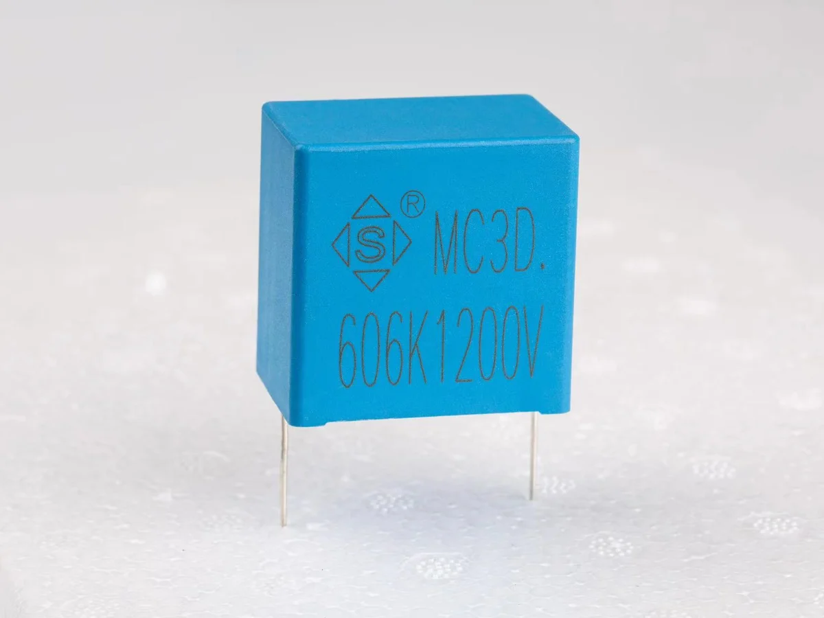
Showing 20 of 20 part numbers
| 3D1U126KV1B0320330180EVT |
|---|
| 3D1U205KV1B0315220130EVT |
| 3D1U335KV1B0320200110EVT |
| 3D1V405KV1A5310250150EVT |
| 3D1X105KV1A5315200110EVT |
| 3D1X106KV1B0320370220EET |
| 3D1X106KV1B0320370220EVT |
| 3D1X855KV1B0320330180EVT |
| 3D1Y104KQ135180210120EVT |
| 3D1Y205KV135315250150EVT |
| 3D1Y205KV1A5315250150EVT |
| 3D1Y205KV1B0315250150EVT |
| 3D1Y206KLMB0420450300EVT |
| 3D1Y505KV1A5315250150EVT |
| 3D2E335JV1B0315200110EVT |
| 3D2H206KV150320370220EV0 |
| 3D2K106KV1B0320370220EVT |
| 3D2K306KLMB0420450300EVT |
| 3D2K505KV150310330180EVT |
| 3D2K505KV150320330180EVT |
Need a value that is not listed? Send us your specification.
Datasheets, technical documents and approval certificates for this series. English editions of documents marked “Chinese” are available on request.
Boxed metallized polypropylene DC-link film capacitors with self-healing construction for DC-bus filtering and energy storage in converters, industrial power supplies and renewable-energy inverters. Rated 500–1,200 VDC; 2–180 µF, maximum value depending on voltage; tolerance ±5% or ±10%. Operating temperature −40 °C to +105 °C, voltage derating above +85 °C. Lead pitch 27.5, 37.5 or 52.5 mm; two- or four-pin PCB mounting.
| Component function | PCB-mount metallized polypropylene DC-link capacitor for DC filtering and energy storage · not an X/Y safety capacitor · not for reflow soldering |
|---|---|
| Construction | Metallized polypropylene film · self-healing · plastic box encapsulation |
| Standards and approvals | No IEC 61071, IEC 60384, AEC-Q200 or agency approval is specified for this series; qualification data on request |
| Rated DC voltage | 500 · 600 · 800 · 900 · 1,000 · 1,200 VDC |
| Capacitance range | 2–180 µF · J ±5% or K ±10%; the maximum value depends on rated voltage |
| Maximum capacitance per voltage | 1,200 V: 25 µF · 1,000 V: 70 µF · 800/900 V: 95 µF · 600 V: 110 µF · 500 V: 180 µF |
| Stored energy | E = ½CV²; 22.5 J at 180 µF / 500 V and 18 J at 25 µF / 1,200 V. Provide discharge and touch protection in the equipment. |
| Capacitance tolerance | ±5% (J) · ±10% (K) |
| Operating temperature | −40 °C to +105 °C |
| Voltage derating | VRDC reduced by 1.25 percentage points per °C from +85 °C to +105 °C; derating curve and hot-spot definition on request |
| Climatic category | 40/85/56; does not define humidity performance under DC bias (THB) |
| Dissipation factor | tan δ ≤0.2% at 1 kHz, 1.0 Vrms, 20 °C |
| Insulation resistance | ≥10,000 MΩ at 100 VDC, 60 s, 20 °C |
| Voltage proof, terminal to terminal | 1.5 × UR, 10 s |
| Lead pitch | V 27.5 · L 37.5 · I 52.5 mm; pitch depends on rated voltage and capacitance |
| Body dimensions | W 31–58 · H 20–65 · T 11–45 mm, ±0.5 mm; case depends on rated voltage and capacitance |
| Lead diameter | 0.8 / 1.0 / 1.2 mm ±0.05 mm, by case and pitch |
| Terminal styles | E single terminal · F double terminal · K upright screw terminal · M four-pin lead. Datasheet drawings cover two- and four-pin PCB versions; drawings for other styles on request. |
| Lead length | Cut to customer requirement · ±0.5 mm for 5–9 mm · ±1.0 mm for 10–20 mm |
| Case material | Plastic case |
| Hand soldering / rework | Iron ≤350 °C · ≤3 s · ≥2 mm from the case |
| Reflow soldering | Not permitted; wave-soldering profile on request |
| Storage | ≤35 °C · ≤70% RH · unopened original package · max. 12 months |
| Storage atmosphere | Protect terminals from hydrogen chloride, hydrogen sulfide and sulfurous atmospheres, which can degrade solderability |
| Further data | On request: metallization and internal construction · permissible Irms versus frequency and ambient temperature, ripple-voltage limit and temperature-rise criterion · ESR, tan δ versus frequency, thermal resistance, hot-spot location and self-heating limit · dV/dt, peak current, pulse energy, short-circuit and failure-mode data · ESL, impedance curve and self-resonant frequency, two-pin versus four-pin · expected life versus voltage, hot-spot temperature and ripple current, FIT rate and end-of-life criteria · THB, damp-heat, altitude, corrosion, thermal-cycling and salt-mist data · mass, board-retention, vibration, lead-current-sharing and torque data · flammability rating and material declarations · loaded-life, ripple-endurance, surge, self-healing, shock, lead-strength, soldering and flame test data |
Ranges by dielectric, package and lead style within this series.
| Variant | Body dimensions | Rated voltage / capacitance | Dielectric / tolerance / package | Lead / land pattern | Notes |
|---|---|---|---|---|---|
| V · 27.5 mm | W 31–32 · H 20–37 · T 11–22 mm | 500–1,200 VDC · lower-energy values | Metallized PP · J/K · boxed DC-link construction | P 27.5 ±1.0 · d 0.8–1.0 ±0.05 mm | Compact PCB case. Do not extrapolate Irms, ESR, thermal or life data from case size. |
| L · 37.5 mm | W 41.5 · H 28–55 · T 14–40 mm | 500–1,200 VDC · medium-energy values | Metallized PP · J/K · two- or four-pin | P 37.5 ±1.0 · d 1.0–1.2 ±0.05 mm | Medium current and energy. Terminal layout, support and current sharing per the part drawing. |
| I · 52.5 mm | W 58 · H 43.5–65 · T 29.5–45 mm | 500–1,200 VDC · higher-energy values; 500 V reaches 180 µF | Metallized PP · J/K · two- or four-pin | P 52.5 ±1.0 · d 1.0–1.2 ±0.05 mm | Highest energy. Validate board support, discharge, Irms, hot spot, vibration and life in the application. |
Start with the converter mission profile, not only bus voltage and capacitance. Coordinate steady-state and transient voltage, stored energy, ripple spectrum, ESR/ESL, hot-spot temperature, cooling, humidity, altitude, lifetime, discharge safety and two- or four-pin mechanics.
Define nominal and maximum DC bus voltage, switching and low-frequency ripple spectra, regenerative or fault overvoltage, precharge and discharge behavior, ambient temperature and cooling, altitude, humidity, vibration and the lifetime histogram.
Select from the voltage/capacitance table in the datasheet and observe the maximum capacitance at each voltage. The 2–180 µF series range does not apply at every voltage.
Calculate harmonic Irms and energy E = ½CV², and check them against the part's ESR versus frequency and temperature, ESL and resonance, Irms, ripple-voltage, terminal-current, Rth, hot-spot and self-heating limits (on request).
Apply the voltage derating above +85 °C and a life model based on voltage, hot spot, ripple, humidity and altitude. THB, loaded and ripple life, FIT rate and end-of-life criteria for the mission profile on request.
Specify W/H/T, pitch, two- or four-pin layout, lead diameter and length, packing and marking for the part number. Define discharge and touch protection, creepage and clearance, mechanical support, wave soldering, cleaning, coating and vibration acceptance.
Initial dissipation factor, insulation resistance and voltage proof are specified, together with voltage derating and dimension tables. ESR, ESL, ripple-current, thermal, THB and lifetime data on request.
| Test | Condition | Acceptance |
|---|---|---|
| Initial characteristics | tan δ ≤0.2% at 1 kHz / 1 Vrms / 20 °C; IR ≥10 GΩ at 100 VDC / 60 s / 20 °C | Measurement details on request |
| Voltage proof, terminal to terminal | 1.5 × UR, 10 s | Ramp, trip current and post-test ΔC, tan δ, IR and visual criteria on request |
DC-link voltage alone does not select the part. Sum harmonic currents using part-level ESR, include terminal current and cooling, and verify the measured hot spot against the life model for the part.
Use E = ½CV² for every operating and fault condition. Define precharge, bleeder or discharge, residual voltage, service isolation and short-circuit protection outside the capacitor.
The series reaches 180 µF only at 500 V; at 1,200 V the maximum is 25 µF. Select from the voltage/capacitance table.
For solar, wind, storage and industrial service, request THB data with applied bias, a voltage, hot-spot and ripple life model, and post-test capacitance, ESR/loss, IR and visual limits.
Two- and four-pin versions can differ in ESL and current sharing. Use the terminal drawing and impedance data for the part; keep busbar and PCB commutation loops short and symmetric.
Large cases need mechanical restraint and vibration validation. Do not reflow-solder; use the wave- or hand-soldering profile specified for the part, and validate cleaning, coating, lead stress and thermal cycling.
Example ordering code. Not every combination is available.
3D · 2K · 106 · J · L · M · B0 · 420 · 450 · 220 · E · V · T
| Code | Meaning |
|---|---|
| 3D | MC3D PCB-mount DC-link series code |
| 2K | Rated voltage: 2K = 800 VDC; 1X = 900, 2H = 500 VDC; other voltage codes on request. |
| 106 | Capacitance code: 106 = 10 µF; 105 = 1 µF, 107 = 100 µF |
| J | Capacitance tolerance: J = ±5%; K = ±10% |
| L | Lead pitch: L = 37.5 mm; V = 27.5, I = 52.5 mm |
| M | Terminal style: M = four-pin lead; E = single terminal, F = double terminal, K = upright screw terminal (drawings on request) |
| B0 | Lead length: B0 = 20.0 mm |
| 420 | Body width: 420 = 42.0 mm |
| 450 | Body height: 450 = 45.0 mm |
| 220 | Body thickness: 220 = 22.0 mm |
| E | Environmental: E = RoHS; F = RoHS + halogen-free |
| V | STE internal management code |
| T | STE internal management code |