
Keep AC and DC ratings separate
Each AC rating is paired with a DC rating, without waveform, frequency or lifetime correlation. Use the rating that matches the application; do not convert by a simple peak or RMS ratio.
| Rated voltage | 400–900 VAC / 1,000–2,000 VDC |
|---|---|
| Capacitance | 1–100 nF |
| Construction | Double-sided metallized PP |
| Tolerance | ±5% / ±10% |
| Lead spacing | 10 / 15 / 22.5 mm |
| Operating temperature | −40 °C to +105 °C |
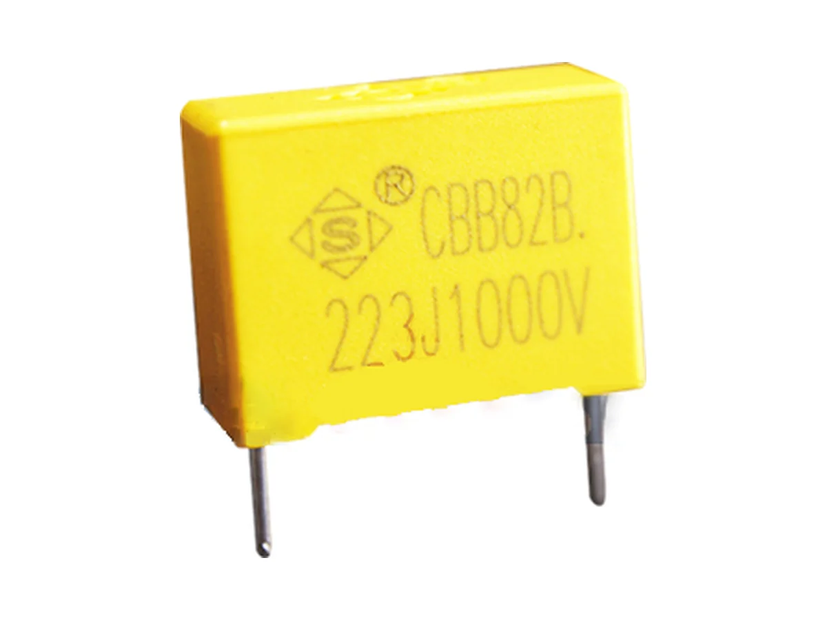
Boxed double-sided metallized polypropylene film capacitors for high-voltage, high-frequency pulse circuits. 400–900 VAC / 1,000–2,000 VDC, 1–100 nF.
Showing 25 of 287 part numbers
| HB2E224JT135260200110EST |
|---|
| HB2E394JT135265170085EST |
| HB2E473JQ1B0180120060EST |
| HB2E474JT135265190100EST |
| HB2E682JN1B0130090040EST |
| HB2H153KQ1B0180120060EST |
| HB2J103JN1B0130110050EST |
| HB2J104JQ132180135075FET |
| HB2J104JQ132180160100EST |
| HB2J104JQ135180135075EST |
| HB2J104JQ135180160100EST |
| HB2J104JQ135180160100FET |
| HB2J104JQ135180190110EST |
| HB2J104JQ1A2180160100EST |
| HB2J104JQ1A5180135075EST |
| HB2J104JQ1A5180160100EST |
| HB2J104JQ1A8180135075EST |
| HB2J104JQ1B0180135075EST |
| HB2J104JQ1B0180160100FET |
| HB2J104JQ1B0180190110ES0 |
| HB2J104JQ1B0180190110EST |
| HB2J104JQ280180190110EST |
| HB2J104JT135265165070EST |
| HB2J105JV1A5310250140EVT |
| HB2J123JN1B0130110050EST |
Need a value that is not listed? Send us your specification.
Datasheets, technical documents and approval certificates for this series. English editions of documents marked “Chinese” are available on request.
Double-sided metallized polypropylene film capacitors in a flame-retardant plastic box, for high-voltage, high-frequency pulse circuits and electronic ballasts. Rated 400 / 500 / 700 / 900 VAC, paired with 1,000 / 1,200 / 1,600 / 2,000 VDC. Capacitance 1–100 nF, J ±5% or K ±10%. Lead spacing 10, 15 and 22.5 mm. Operating temperature −40 °C to +105 °C.
| Product type | Boxed double-sided metallized polypropylene capacitor for high-voltage, high-frequency pulse duty |
|---|---|
| Construction | Polypropylene dielectric · double-sided metallized electrodes · plastic box |
| Self-healing | Not specified |
| Rated AC voltage | 400 · 500 · 700 · 900 VAC |
| Rated DC voltage | 1,000 · 1,200 · 1,600 · 2,000 VDC, paired with 400 · 500 · 700 · 900 VAC |
| Capacitance range | 1–100 nF · max. 27 nF at 500 and 700 VAC · 18 nF at 900 VAC |
| Capacitance tolerance | J ±5% · K ±10% |
| Operating temperature | −40 °C to +105 °C |
| Climatic category | 40/100/21 · derating between +100 °C and +105 °C on request |
| Storage temperature | +15 °C to +35 °C |
| Dissipation factor | tan δ ≤0.1% at 1 kHz, 1.0 Vrms, 20 °C |
| Insulation resistance | ≥50,000 MΩ at 100 VDC, 60 s, 20 °C |
| Voltage proof, terminal to terminal | 1.75 × UR for 5 s (UR basis: see datasheet) |
| Temperature coefficient of capacitance | Negative |
| Safety class | No X/Y class and no agency approval; do not use across the line or line to earth |
| Flame retardancy | Flame-retardant plastic box |
| Body dimensions | W max. 13–26 · H max. 9–20 · T max. 4–11 mm, depending on voltage and capacitance |
| Lead spacing | 10 · 15 · 22.5 mm, ±1.0 mm |
| Lead diameter | 0.6 ±0.05 mm at 10 mm spacing · 0.8 ±0.05 mm at 15 / 22.5 mm spacing |
| Lead forms and packing | Long straight · inner-bent · straight taped · bent taped |
| Taping | Tape dimensions specified for F = 10, 15 and 20–22.5 mm |
| Soldering profile, PP | Preheat ≤110 °C · soldering ≤120 °C · ≤15 s |
| Soldering profile, PE | Preheat ≤125 °C · soldering ≤160 °C · ≤15 s |
| Hand soldering | 350 °C max. · 3 s max. · ≥2 mm from the coating |
| Reflow soldering | Not permitted; film shrinkage can degrade performance |
| Environmental compliance | RoHS and REACH compliant; bromine-free and halogen-free. Material declarations on request. |
| Further data | On request: internal series connection and segmentation · self-healing and fault response · AC frequency, waveform and current limits · storage humidity and shelf life · frequency range, impedance, ESR, ESL and permissible voltage and current versus frequency · dV/dt, K0, peak, repetitive and RMS current, thermal resistance and hot-spot limit · capacitance-temperature curve · UL 94 class · pulse-life, AC endurance, damp-heat, overload, thermal-cycle, vibration and lead-strength test results |
Ranges by dielectric, package and lead style within this series.
| Variant | Body dimensions | Rated voltage / capacitance | Construction / tolerance | Lead / land pattern | Notes |
|---|---|---|---|---|---|
| N · 10 mm | W max. 13 · H max. 9–13 · T max. 4–7 mm | 400 VAC / 1,000 VDC · 1–5.6 nF | Double-sided metallized PP · J/K | P 10 ±1.0 · d 0.6 ±0.05 mm | Smallest body; 400 VAC / 1,000 VDC only. |
| Q · 15 mm | W max. 18 · H max. 11–16.5 · T max. 5–10 mm | 400 VAC: 6.8–27 nF · 500 VAC: 1–15 nF · 700 VAC: 1–6.8 nF | Double-sided metallized PP · J/K | P 15 ±1.0 · d 0.8 ±0.05 mm | Check waveform, dV/dt, RMS current and hot-spot limit per part number. |
| T · 22.5 mm | W max. 26 · H max. 13.5–20 · T max. 6–11 mm | 400 VAC: 33–100 nF · 500/700 VAC to 27 nF · 900 VAC: 1–18 nF | Double-sided metallized PP · J/K | P 22.5 ±1.0 · d 0.8 ±0.05 mm | Highest voltage and capacitance values; check AC and pulse endurance, vibration, board support and fault response per part number. |
Start with the AC or DC waveform and the resonant mission profile. Then check voltage basis, capacitance, dV/dt, peak and RMS current, frequency, hot-spot rise, fault response, lifetime and dimensions.
Specify DC bias, AC fundamental, peak voltage, rise and fall time, dV/dt, repetition rate, RMS current, harmonics, start-up or ignition, open-load and abnormal transients, together with ambient temperature, cooling and service hours.
The series covers 400/500/700/900 VAC, paired with 1,000/1,200/1,600/2,000 VDC, at 1–100 nF. Do not substitute one rating basis for the other; request the specification for any other rating.
Use Ipk = C·dV/dt and the measured spectrum to calculate peak, repetitive and RMS current, and check them against the dV/dt, K0, ESR, ESL, impedance, resonance, thermal-resistance and frequency-derating data (on request).
Check the electrode stack, internal series connection, self-healing behavior and fault response of the selected part number, together with its AC and pulse endurance, humidity and overload test data.
Match voltage, capacitance, tolerance, W/H/T, lead spacing, lead form, packing and soldering profile to the part number. Do not use reflow soldering; validate lead forming and vibration.
Each AC rating is paired with a DC rating, without waveform, frequency or lifetime correlation. Use the rating that matches the application; do not convert by a simple peak or RMS ratio.
Double-sided metallization can be built with different carrier films, internal series structures and margins. Before relying on self-healing, fail-open behavior or overload capability, request the construction and fault-response data of the selected part.
Measure the actual voltage and current spectrum, including ignition and abnormal modes. Combine I = C·dV/dt with RMS current, ESR and thermal resistance to verify hot-spot rise and resonance margin.
Record switching frequency, ignition pulse, lamp-open and end-of-life behavior, enclosure temperature and target service hours. Validate the selected part number over the complete operating sequence.
For other voltage ratings, values above 100 nF or below 1 nF, or 7.5 and 27.5 mm lead spacing, request the part specification, drawing and qualification report. Do not extrapolate.
Apply the PP/PE soldering limits to the actual construction and do not use reflow soldering. Keep lead-forming stress away from the epoxy seal, and validate cleaning, coating, vibration and thermal cycling, especially for the 26 mm body.
Example ordering code. Not every combination is available.
HB · G2 · 153 · J · Q · 1 · B0 · 180 · 120 · 060 · E · S · 0
| Code | Meaning |
|---|---|
| HB | Series code: MMKP82/CBB82B |
| G2 | Rated voltage code: G2 = 400 VAC; H2 = 500 VAC, V1 = 700 VAC, X1 = 900 VAC; DC voltage codes on request |
| 153 | Capacitance code: 153 = 15 nF |
| J | Capacitance tolerance: J = ±5%, K = ±10% |
| Q | Lead spacing: Q = 15 mm; N = 10 mm, T = 22.5 mm |
| 1 | Lead form: 1 = long straight, 2 = inner-bent, 5 = straight taped, 6 = bent taped |
| B0 | Lead length code: B0 = 20.0 mm |
| 180 | Body width: 180 = 18.0 mm |
| 120 | Body height: 120 = 12.0 mm |
| 060 | Body thickness: 060 = 6.0 mm |
| E | Environmental code: E = RoHS, F = RoHS and halogen-free |
| S | STE internal control code, first field |
| 0 | STE internal control code, second field |