
Y2 does not provide reinforced insulation
Use line to protective earth or another bypass position only where Y2 basic or supplementary insulation is permitted. Reinforced barriers require Y1.
| Safety class | Y2, line-to-earth |
|---|---|
| Automotive qualification | AEC-Q200 Rev E qualified part numbers available |
| Rated voltage | 250 / 275 / 300 / 350 VAC |
| Capacitance | 0.001–1.2 µF |
| Tolerance | ±10% / ±20% |
| Temperature cycling | 1,000 cycles, −55 °C to +110 °C |





Automotive boxed metallized polypropylene film capacitors, Class Y2, for line-to-earth EMI suppression. 250–350 VAC; 1 nF–1.2 µF; AEC-Q200 Rev E qualified part numbers available.
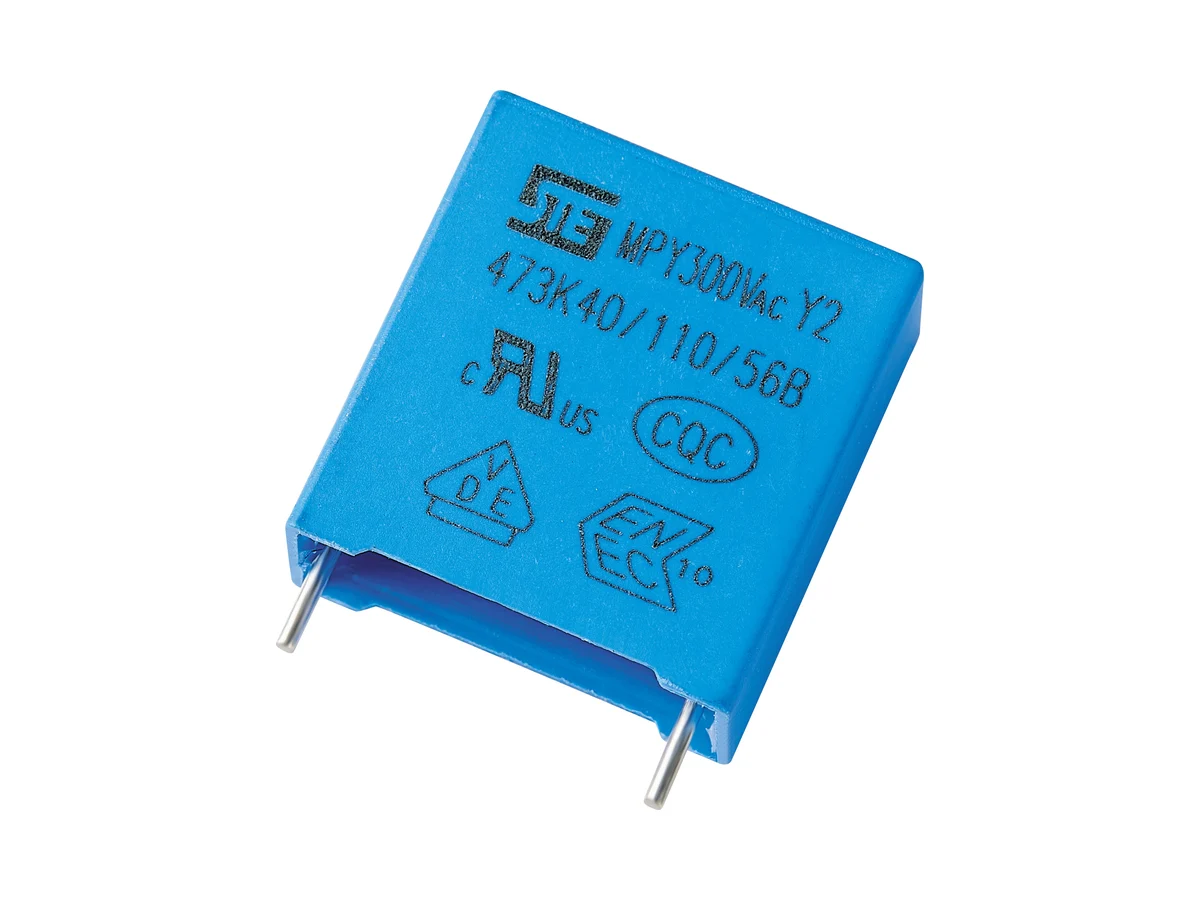
Showing 25 of 26 part numbers
| Y2Q1102KJ1B0100090040EVG | 0.001 | ±10 | 300 | Y2 |
|---|---|---|---|---|
| Y2Q1102KN135130090040EVG | 0.001 | ±10 | 300 | Y2 |
| Y2Q1102KN135130090040EVG-02 | 0.001 | ±10 | 300 | Y2 |
| Y2Q1102KN150130090040EVG | 0.001 | ±10 | 300 | Y2 |
| Y2Q1102KN150130090040EVG-02 | 0.001 | ±10 | 300 | Y2 |
| Y2Q1102KN1B0130110050EVG | 0.001 | ±10 | 300 | Y2 |
| Y2Q1152KJ1A5100090040EVG | 0.0015 | ±10 | 300 | Y2 |
| Y2Q1222KJ135100110050EVG | 0.0022 | ±10 | 300 | Y2 |
| Y2Q1332KNHB0130110050EVG | 0.0033 | ±10 | 300 | Y2 |
| Y2Q1472KN1A5130110050EVG | 0.0047 | ±10 | 300 | Y2 |
| Y2Q1472KN1B5130110050EVG | 0.0047 | ±10 | 300 | Y2 |
| Y2Q1473KQ135180190080EVG | 0.047 | ±10 | 300 | Y2 |
| Y2Q1473KQ135180190080EVG-02 | 0.047 | ±10 | 300 | Y2 |
| Y2Q1473KQ150180190080EVG | 0.047 | ±10 | 300 | Y2 |
| Y2Q1473KQ150180190080EVG-02 | 0.047 | ±10 | 300 | Y2 |
| Y2Q1473KT1B5265150060EVG | 0.047 | ±10 | 300 | Y2 |
| Y2Q1683KQ1B0180190110EVG | 0.068 | ±10 | 300 | Y2 |
| Y2Q1104KT135265170085EVG | 0.1 | ±10 | 300 | Y2 |
| Y2Q1104KT1A5265170085EVG | 0.1 | ±10 | 300 | Y2 |
| Y2Q1104KT1B0265170085EVG | 0.1 | ±10 | 300 | Y2 |
| Y2Q1124KT1B5265190100EVG | 0.12 | ±10 | 300 | Y2 |
| Y2Q1154KV135315195108EVG | 0.15 | ±10 | 300 | Y2 |
| Y2Q1184KT1B5260200110EVG | 0.18 | ±10 | 300 | Y2 |
| Y2Q1224KT135260215120EVG | 0.22 | ±10 | 300 | Y2 |
| Y2Q1224KT1B0260215120EVG | 0.22 | ±10 | 300 | Y2 |
— = not specified
Need a value that is not listed? Send us your specification.
Datasheets, technical documents and approval certificates for this series. English editions of documents marked “Chinese” are available on request.
Automotive boxed metallized polypropylene film capacitors for line-to-earth (L/N–PE) EMI suppression, Class Y2 to IEC 60384-14, for basic or supplementary insulation. AEC-Q200 Rev E qualified part numbers available; temperature cycling 1,000 cycles, −55 °C to +110 °C. Rated 250, 275, 300 and 350 VAC; 1 nF–1.2 µF; tolerance ±10% or ±20%. Climatic category 40/110/56B.
| Product role | Automotive Class Y2 line-to-earth / line-bypass interference-suppression capacitor |
|---|---|
| Construction | Boxed metallized polypropylene film |
| Safety / insulation function | Class Y2 to IEC 60384-14 for basic or supplementary insulation where the equipment standard permits it · not for reinforced-insulation (Y1) positions |
| Automotive qualification | AEC-Q200 Rev E qualified part numbers available; qualified part-number list, qualification report and temperature grade on request |
| Temperature cycling | 1,000 cycles, −55 °C to +110 °C |
| Climatic category | 40/110/56B (lower category temperature −40 °C; −55 °C is a temperature-cycling test condition) |
| Rated AC voltages | 250 · 275 · 300 · 350 VAC |
| Capacitance range | 0.001–1.2 µF; available values depend on rated voltage and pitch |
| Capacitance tolerance | ±10% (K) · ±20% (M, on request) |
| Dissipation factor | tan δ ≤0.15% |
| Insulation resistance | CR ≤0.33 µF: ≥15,000 MΩ · CR >0.33 µF: R × C ≥5,000 s · 20 °C / 100 VDC / 60 s |
| Voltage proof, terminal to terminal | 1,500 VAC, 1 s, or 3,500 VDC, 5 s |
| Voltage proof, terminals to case | 2 × UR + 1,500 VAC, min. 2,000 VAC |
| Impulse sequence | 24 pulses · 9 s charge / 2 s discharge |
| Self-ignition test | U = UR · U1 = 5.0 kV · 20 discharges of the energy-storage capacitor per sample · 5 s interval |
| UL / cUL approval | UL 60384-14 · E208107 · MPY 0.001–1.2 µF at 250/275/300/350 VAC |
| VDE / ENEC approval | EN 60384-14:2013 + A1:2016 · 40056386 · no Annex H (DC) approval; no Annex I humidity grade |
| CQC approval | CQC23001379254 · MPY safety approval |
| IECEE CB certificate | DE1-67208 · test report 300758-TL3-1 |
| Maximum capacitance per pitch | 7.5 mm to 3.9 nF · 10 mm to 10 nF · 15 mm to 47 nF · 22.5 mm to 100 nF · 27.5 mm to 330 nF · 37.5 mm to 1.2 µF |
| Voltage codes | E2 250 · P2 275 · Q1 300 · R2 350 VAC |
| Pitch codes | N 10 · Q 15 · T 22.5 · V 27.5 mm; 7.5 and 37.5 mm codes on request |
| Lead, environmental and color codes | 1 long straight · 2 inner-bent · 5 straight taped · 6 bent taped · E RoHS · F RoHS + halogen-free · V blue · E gray |
| Automotive suffix | G in the last position of the part number = automotive product |
| Body dimensions | W 10–41.5 · H 9–41 · T 4–27.5 mm · P ±0.5 mm · lead diameter ±0.05 mm; dimensions depend on rated voltage and capacitance |
| Lead diameter | Ø0.6 mm at 7.5 / 10 mm pitch · Ø0.8 mm at 15 / 22.5 / 27.5 mm · Ø1.0 mm at 37.5 mm |
| Lead forms and taping | Drawings for long straight and inner-bent leads and carrier tape in the datasheet; other lead codes and 5 mm taping on request |
| Soldering limits (body temperature) | PP: preheat ≤110 °C, soldering ≤120 °C for ≤15 s · PE: preheat ≤125 °C, soldering ≤160 °C for ≤15 s; applicable limit (PP or PE) on request |
| Wave and hand soldering | Board profile 260 °C max., peak <10 s, cooling ≤5 °C/s · iron ≤350 °C, ≤3 s, ≥2 mm from the case |
| Reflow soldering | Not permitted; film shrinkage can degrade performance |
| Storage and atmosphere | ≤35 °C · ≤70% RH · ≤12 months unopened; avoid hydrogen chloride, hydrogen sulfide and sulfur compounds, which degrade solderability |
| Humidity (THB) | No THB rating; the VDE approval includes no Annex I humidity grade |
| Leakage current | Calculate at system level from capacitance, tolerance, mains voltage and frequency |
| Further data on request | Metallization design and end-of-life behavior · continuous operating range and voltage derating · tan δ measurement conditions · terminal-to-case voltage-proof duration and method · impulse test voltage and circuit · test details, energy, pass criteria and post-test limits for temperature cycling, impulse and self-ignition tests · biased 85/85 humidity data · failure-current data · ESR/impedance, RMS and peak current, dV/dt, hot-spot temperature, thermal resistance and lifetime · PPAP, traceability, production screening and change notification |
Ranges by dielectric, package and lead style within this series.
| Variant | Body dimensions | Rated voltage / capacitance | Construction / class / tolerance | Lead / land pattern | Notes |
|---|---|---|---|---|---|
| N · 10 mm | W 13 · H 9–15 · T 4–7 mm | 250–350 VAC · 0.001–0.01 µF | Metallized PP · Y2 · K/M | P 10 ±0.5 · Ø0.6 ±0.05 mm | Compact case for low capacitance values. |
| Q · 15 mm | W 18 · H 12–21 · T 6–12 mm | 250–350 VAC · 0.01–0.047 µF | Metallized PP · Y2 · K/M | P 15 ±0.5 · Ø0.8 ±0.05 mm | — |
| T · 22.5 mm | W 26 · H 17–23 · T 8.5–13 mm | 250–350 VAC · 0.047–0.1 µF | Metallized PP · Y2 · K/M | P 22.5 ±0.5 · Ø0.8 ±0.05 mm | — |
| V · 27.5 mm | W 31–31.5 · H 20–30.5 · T 11–22 mm | 250–350 VAC · 0.1–0.33 µF | Metallized PP · Y2 · K/M | P 27.5 ±0.5 · Ø0.8 ±0.05 mm | Check the leakage current. |
Confirm that Class Y2 is permitted in the actual insulation architecture and calculate the total leakage current. Then specify one G-suffix part number whose AEC-Q200 report, safety approvals, voltage, capacitance, body, suffix and lead-form meaning, current and thermal limits, packing and process all match the application.
Use line to protective earth or another bypass position only where Y2 basic or supplementary insulation is permitted. Use Y1 for reinforced insulation or the higher impulse requirement.
Use maximum capacitance including tolerance, line voltage and frequency, then sum every Y capacitor and other leakage path against the normal and single-fault equipment limits.
Request the AEC-Q200 Rev E report for the selected part number, with qualified part numbers, grade, site, lots, results and requalification record, and the current safety certificates for the same construction and marking.
Obtain the drawing and code definition for part numbers with the suffix −02 or other lead codes, and for values above the maximum per pitch. Then coordinate AC, impulse, humidity, vibration, current, hot spot and life.
Confirm the G suffix, drawing, marking, body and lead geometry, packing and PP/PE construction with STE. Validate spacing, soldering, cleaning and coating, storage, screening and traceability.
AEC-Q200 is a stress-test qualification for automotive components; IEC 60384-14 approvals cover the Y2 safety function separately. Approval and AEC-Q200 coverage of individual G-suffix part numbers, including suffix −02 versions, on request.
| Agency | Standard | Certificate | Scope |
|---|---|---|---|
| UL / cUL | UL 60384-14 | E208107 | MPY Y2, 0.001–1.2 µF, 250–350 VAC |
| IECEE CB | IEC 60384-14:2013 + AMD1:2016 | DE1-67208 | MPY Y2, test report 300758-TL3-1 |
Each certificate covers the types and ratings listed on it.
Initial electrical limits, AEC-Q200 Rev E qualification, temperature cycling (1,000 cycles, −55 °C to +110 °C), an impulse test sequence and a self-ignition test are specified.
| Test | Condition | Acceptance |
|---|---|---|
| Temperature cycling | 1,000 cycles, −55 °C to +110 °C | Dwell time, sample size and post-test ΔC, tan δ, IR, voltage-proof and visual limits on request |
| Initial characteristics and voltage proof | tan δ ≤0.15%; IR ≥15 GΩ or RC ≥5,000 s; voltage proof terminal to terminal and terminals to case | Measurement conditions and voltage-proof method on request |
Use line to protective earth or another bypass position only where Y2 basic or supplementary insulation is permitted. Reinforced barriers require Y1.
Sum all Y capacitors and leakage paths at maximum capacitance, voltage and frequency against the normal and single-fault equipment limit.
Map the AEC-Q200 report and the current safety certificates to the same G-suffix construction and manufacturing site.
Obtain the impulse test voltage, circuit and the complete impulse and self-ignition report from STE before setting an application limit.
Validate creepage and clearance, protective earth, fusing, soldering, cleaning and coating, vibration and open- and short-circuit behavior. Do not reflow-solder.
Example ordering code. Not every combination is available.
Y2 · Q1 · 103 · K · Q · 1 · B0 · 180 · 120 · 060 · E · V · G
| Code | Meaning |
|---|---|
| Y2 | Safety class Y2 and MPY series |
| Q1 | Rated voltage: Q1 = 300 VAC; E2 = 250, P2 = 275, R2 = 350 VAC |
| 103 | Capacitance code: 103 = 10 nF |
| K | Capacitance tolerance: K = ±10%; M = ±20% |
| Q | Lead pitch: Q = 15 mm; N = 10, T = 22.5, V = 27.5 mm. 7.5 and 37.5 mm codes on request. |
| 1 | Lead form: 1 = long straight; 2 = inner-bent, 5 = straight taped, 6 = bent taped. Other lead codes on request. |
| B0 | Lead length: B0 = 20.0 mm. Three-character length codes on request. |
| 180 | Body width: 180 = 18.0 mm |
| 120 | Body height: 120 = 12.0 mm |
| 060 | Body thickness: 060 = 6.0 mm |
| E | Environmental: E = RoHS; F = RoHS + halogen-free |
| V | Case color: V = blue; E = gray |
| G | G = automotive product. Meaning of the suffix −02 on request. |