CY

CY Series Safety Certified Disc Ceramic Capacitors (Class X1/Y1)

Safety classX1 / Y1 (IEC 60384-14)
Rated voltageX1 760 VAC · Y1 500 VAC · 1,500 VDC (Y5U/Y5V)
Capacitance100–10,000 pF
Lead spacing10.0 mm
Operating temperature−40 °C to +125 °C
ApprovalsCQC · VDE/ENEC · UL/cUL
UL certification markVDE certification markENEC certification markCQC certification mark

Leaded disc ceramic safety capacitors, Class X1/Y1 to IEC 60384-14. X1 up to 760 VAC, Y1 up to 500 VAC, 100–10,000 pF.

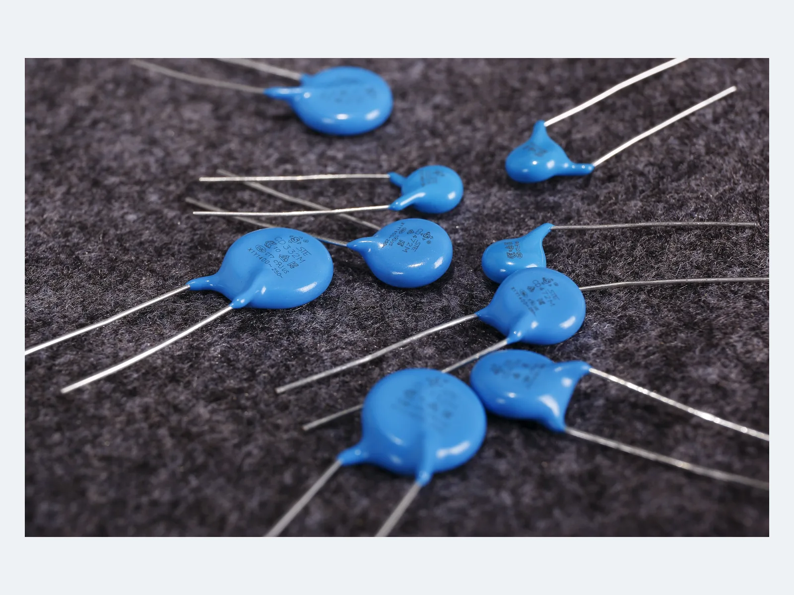
Typical appearance, Y1 safety ceramic capacitors

Part numbers

83

Showing 25 of 83 part numbers

Q07B1D101KN0B0C0N0
Q07B1D151KN0B0C0N0
Q07B1D221KN0B0C0N0
Q07B1D471KN0B0C0N0
Q07B2D101KP0T2CQPW
Q07B3D101KA5B0C0N0
Q07B8D101KP0T2C0P0
Q07B8D101KP0T2K0P0
Q07B8D151KP0T2C0P0
Q07B8D221KP0T2C0P0
Q07E1D331KN0B0C0N0
Q07E8D471KP0T2C0P0
Q07F8D102MP0T2C0P0
Q08B8D331KP0T2C0P0
Q08E1D102MN0B0C0N0
Q08E1D102MN0B2CQN0
Q08E1D681KN0B0C0N0
Q08E2D102MB0B0C0N0
Q08E2D102MP0P2CQAW
Q08E2D102MP0T2C0P0
Q08E3D102MA0B2CQN0
Q08E3D102MA5B2CQN0
Q08E8D102MN0B0C0N0
Q08E8D102MP0T2C0P0
Q08E8D681KP0T2C0P0

Need a value that is not listed? Send us your specification.

Engineering details

Overview

Leaded disc ceramic safety capacitors, Class X1/Y1 to IEC 60384-14, for line-to-line, line-to-earth and reinforced-insulation EMI suppression. X1 up to 760 VAC, Y1 up to 500 VAC, 100–10,000 pF. Designated Y5U and Y5V constructions are certified for 1,500 VDC. Operating temperature −40 °C to +125 °C.

Series features

  • Class X1/Y1 for mains EMI suppression and reinforced-insulation positions
  • X1 up to 760 VAC and Y1 up to 500 VAC within the approval scope
  • 1,500 VDC approval for designated Y5U and Y5V constructions
  • Dielectrics Y5P, Y5U and Y5V, 100–10,000 pF
  • Flame-retardant epoxy-coated radial construction, −40 °C to +125 °C
Specifications
Safety classX1 / Y1 · IEC 60384-14
Rated voltage, X1760 · 500 · 440 · 400 VAC
Rated voltage, Y1500 · 400 · 250 VAC
Rated DC voltage1,500 VDC · designated Y5U / Y5V only
Capacitance range100–10,000 pF, depending on dielectric
Capacitance by dielectricY5P 100–2,200 pF · Y5U 330–4,700 pF · Y5V 1,000–10,000 pF
Capacitance toleranceK ±10% · M ±20%, depending on part
Operating temperature−40 °C to +125 °C
Climatic category40/125/21
Passive flammabilityClass B · flame-retardant epoxy coating
Measuring conditions25 °C · 1 kHz · 1 Vrms
Dissipation factor≤2.5%
Insulation resistance≥10,000 MΩ
Dielectric strength4,000 VAC · test conditions per datasheet
Lead spacing10.0 ±0.5 mm
Lead diameter0.60 or 0.65 ±0.05 mm, depending on part
Body dimensionsD max. 7.0–17.5 mm · T max. 4.5–6.0 mm, depending on part
Impulse, endurance and damp-heat dataOn request
Environmental complianceRoHS · REACH · bromine-free / halogen-free
Variants

Ranges by dielectric, package and lead style within this series.

VariantBody dimensionsCertified capacitance rangeTolerance / DC ratingLead / land patternNotes
Y5PD max. 7.0–17.5 · T max. 4.5–6.0 mm100–2,200 pFK ±10% · AC ratings only; no 1,500 VDC ratingF 10.0 ±0.5 · d 0.60/0.65 ±0.05 mmLower-capacitance EMI and coupling positions where temperature stability matters more than maximum value.
Y5UD max. 7.0–15.5 · T max. 5.5–6.0 mm330–4,700 pFK ±10% or M ±20% · 1,500 VDC for designated partsF 10.0 ±0.5 · d 0.60/0.65 ±0.05 mmMid-range capacitance with AC ratings and 1,500 VDC for designated parts.
Y5VD max. 7.0–16.5 · T max. 5.5–6.0 mm1,000–10,000 pFM ±20% · 1,500 VDC for designated partsF 10.0 ±0.5 · d 0.60/0.65 ±0.05 mmHighest capacitance; check effective capacitance and leakage-current margin with particular care.
Selection guide

Start from the circuit position and insulation requirement in the equipment standard. Then define AC/DC voltage, impulse duty, leakage current (set by capacitance), dielectric behavior and approval scope. A dual X1/Y1 marking does not replace qualification of the ordered part in its operating environment.

  1. Classify the circuit position

    Identify line-to-line, line-to-earth or primary-to-secondary use from the end-equipment standard. Y1 bridges reinforced insulation; the insulation diagram and overvoltage category of the equipment govern the choice.

  2. Define AC, DC and impulse duty

    Choose the X1 and Y1 voltage combination, then include repetitive peaks and abnormal transients. The 1,500 VDC approval applies only to designated Y5U/Y5V constructions, not to Y5P.

  3. Set the capacitance limit from leakage current

    Calculate line-frequency current and touch/leakage current at maximum mains voltage and frequency, including tolerance. Use the lowest capacitance that meets the common-mode attenuation target.

  4. Choose dielectric and tolerance

    Y5P, Y5U and Y5V cover different value ranges and temperature characteristics. Data on capacitance versus temperature, voltage and frequency is available on request when the circuit depends on effective rather than nominal capacitance.

  5. Confirm mechanical and approval codes

    Confirm disc diameter, thickness, lead diameter, lead form, bulk or tape packaging, environmental code and approvals for the final part number before PCB and BOM release.

Approvals & reliability

Approvals & qualifications

Approval scopes differ by dielectric, capacitance, voltage and tolerance.

AgencyStandardCertificateScope
CQC certification markCQCIEC 60384-14:2013 + AMD1:2016CQC23001374885CY X1/Y1, 100–10,000 pF; X1 760/500/440/400 VAC, Y1 500/400/250 VAC; Y5P/Y5U/Y5V, tolerance K/M, climatic category 40/125/21, passive flammability class B; Annex H for Y5U/Y5V. Issued 28 Jan 2023, valid subject to surveillance.
VDE certification markENEC certification markVDE / ENECDIN EN 60384-14 / EN 60384-1440056133CY X1/Y1 with the AC ratings above, 100–10,000 pF. Annex H: 1,500 VDC for Y5U/Y5V only. No Annex I humidity-robustness grade is assigned.
UL certification markUL / cULUL 60384-14 / Canadian component recognitionE208107Recognized component, USA and Canada: X1 400/440/500/760 VAC, Y1 250/400/500 VAC; Y5P 100–2,200 pF; higher-K constructions 330–10,000 pF, including 1,500 VDC.

Each certificate covers the types and ratings listed on it.

Design notes

Y1 selection starts with the insulation diagram

Use Y1 only where the equipment standard, rated mains voltage, overvoltage category, pollution degree, creepage and clearance support the complete reinforced-insulation system. The capacitor approval does not cover the surrounding PCB or enclosure.

Capacitance sets line-frequency current

For line-to-earth use, calculate I = 2πfCV at maximum frequency, voltage and capacitance tolerance. Check the result against touch-current and leakage-current limits before using values near 10 nF.

1,500 VDC depends on the dielectric

The DC approval (VDE Annex H) is limited to Y5U and Y5V. The 4 kVAC dielectric-strength test is neither a DC working rating nor an impulse rating.

Impulse and damp-heat data

Impulse waveform and level, endurance and 85 °C / 85% RH test data are available on request when surge or high-humidity lifetime is design-critical. No Annex I humidity-robustness grade is assigned.

Soldering, storage and lead stress

Hand rework: iron 350 °C max., 3 s max., at least 2 mm from the coating. Store unopened parts for up to 12 months at ≤35 °C and ≤70% RH, away from corrosive gases. Form and support leads without loading the ceramic body.

Part numbering

Example ordering code. Not every combination is available.

Q · 09 · F · 1 · D · 222 · M · N0 · B · 0 · C · 0 · N · 0

CodeMeaning
QRated-voltage family code (Y1)
09Body diameter code: 09 = 9 mm
FTemperature characteristic: F = Y5V
1Lead form: 1 = long straight leads
DLead spacing: D = 10.0 mm
222Capacitance code: 222 = 2,200 pF
MCapacitance tolerance: M ±20%
N0Lead length or tape seating-height code, depending on packaging
BPackaging: B = bulk, T = tape
0Environmental code: 0 = RoHS; a RoHS + halogen-free code is also defined
CApproval voltage combination code: C or K, by required AC/DC rating
0 · N · 0Internal management codes