STE Highlights Low Profile SMD-X1Y1 Safety Capacitors
Original report
STE edition
Chongdiantou highlights STE SMD-X1Y1 ceramic safety capacitors for compact assemblies. Package-specific specifications clarify capacitance options, dimensional tolerances and electrical test conditions.
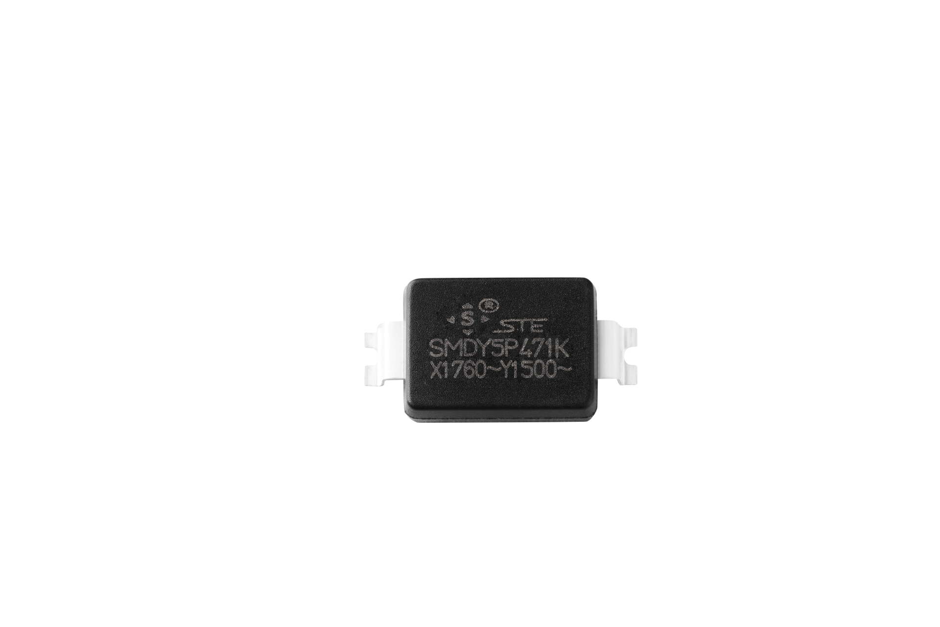
STE's SMD-X1Y1 ceramic safety capacitors were featured in a January 2025 Chongdiantou article on compact power-supply components. The report emphasized low-profile surface mount packaging, tape-and-reel handling and the potential to integrate a Y capacitor into an SMT assembly process.
The family offers alternatives to upright leaded components where enclosure height and board layout are important. The original article named the 3225, 3222 and 4522 outlines and described capacitance options extending to 4700 pF. Those values belong to specific packages and dielectric options; they should not be treated as interchangeable configurations.
Package dimensions need their tolerances
The original coverage described a maximum height of 2.5 mm. The applicable drawings instead specify 2.5 ± 0.3 mm for the packages below. This makes 2.8 mm the upper body-height limit, before allowing for solder, the board and enclosure clearances.
The March 2025 specifications provide later clarification of the January report. The 4522 specification is dated September 26, 2024.
| Outline | Listed capacitance options | Body dimensions | Datasheet revision |
|---|---|---|---|
| 3225 | 10–2200 pF, depending on dielectric | 8.1 ± 0.3 × 6.0 ± 0.3 × 2.5 ± 0.3 mm | March 22, 2025 |
| 3222 | 10–2200 pF, depending on dielectric | 8.1 ± 0.3 × 5.5 ± 0.3 × 2.5 ± 0.3 mm | March 22, 2025 |
| 4522 | 3300 and 4700 pF | 11.5 ± 0.3 × 6.1 maximum × 2.5 ± 0.3 mm | September 26, 2024 |
These are body dimensions. Terminal geometry and the recommended land pattern must be checked separately. The numerical outline designation should not be interpreted as a generic metric chip size.
Electrical limits and approval context
The cited specifications identify Y1 operation at a rated voltage of 500 VAC and an operating temperature range of −40 to +125 °C. They also describe a terminal-to-terminal withstand test of 4000 VAC rms for 60 seconds. The higher test voltage is not a permitted continuous operating voltage.
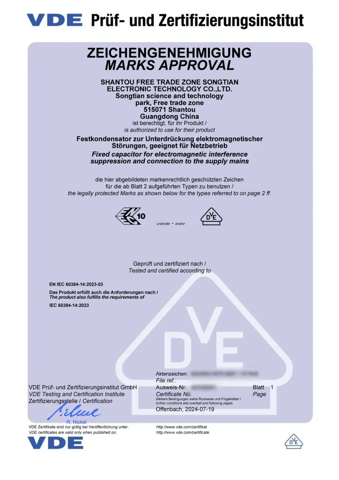
The original article discussed VDE and ENEC approval. The cited 3225 and 3222 specifications include VDE/ENEC information under certificate number 40058861. Exact part coverage and current certificate status must be confirmed for the intended application. Neither component approval nor a compact package establishes that the surrounding PCB or completed power supply meets its safety requirements.
Chongdiantou also reported high-temperature/high-humidity testing and 1000 thermal-shock cycles associated with AEC-Q200. A reported thermal-shock test is not evidence that every part has completed the full qualification program. Application decisions require the relevant test report, conditions and part identification.
Assembly and layout considerations
The report presented tape-and-reel packaging and horizontal mounting as advantages for automated assembly. These features can support an SMT production flow, but actual yield, throughput and cost depend on the board, process and qualification results.
It also suggested locating the capacitor away from heat-producing components. That is a useful layout consideration rather than a guaranteed reliability improvement: moving a component can change both its temperature and the path taken by noise current. Review the electrical routing, insulation spacing and thermal environment together.
The January feature included an announcement for the spring 2025 Asia Charging Expo. This is historical context. Engineers evaluating the family today can consult the SMD-X1Y1 product page and request documentation for the intended capacitance, dielectric and outline. SMD-X1Y1 product page
Technical references
- STE SMD-X1Y1 3225 specification, revision 2025-03-22, pp. 4–6.
- STE SMD-X1Y1 3222 specification, revision 2025-03-22, pp. 4–6.
- STE SMD-X1Y1 4522 specification, revision 2024-09-26, pp. 4–6.
Figures and tables from the original report
The following figures retain their original captions, markings and historical context. Transcribed tables present the values shown in the published images; product selection should use the specifications for the selected part.
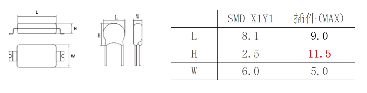
| Dimension | SMD X1Y1 | Leaded (max.) |
|---|---|---|
| L | 8.1 | 9.0 |
| H | 2.5 | 11.5 |
| W | 6.0 | 5.0 |
| Parameter | Value in the source image |
|---|---|
| Type | SMD |
| Capacitor class | Y1: X1Y1 |
| Package dimensions | 3225 ≈ 8.1 × 6.0 mm; 3222 ≈ 8.1 × 5.5 mm; 4522 ≈ 11.4 × 5.5 mm |
| Temperature characteristic: SL | +350 ~ −1000 ppm/°C |
| Temperature characteristic: Y5P | ±10% |
| Temperature characteristic: Y5U | +22% ~ −56% |
| Temperature characteristic: Y5V | +30% ~ −80% |
| Capacitance codes | 100: 10 pF; 101: 100 pF; 102: 1000 pF |
| Capacitance tolerance | K: ±10%; M: ±20% |
| Parameter | Value in the source image |
|---|---|
| Capacitor class | X1Y1 |
| Climatic category | 40/125/21 B |
| Operating temperature | −40°C ~ 125°C |
| Rated voltage | 500 VAC |
| Capacitance range | 10 pF ~ 4700 pF |
| Dissipation factor | S (SL): D.F. ≤ 0.15%; B (Y5P), E (Y5U), F (Y5V): D.F. ≤ 2.5% |
| Dielectric test: terminals to case | 4000 VAC (rms) / 60 sec |
| Dielectric test: between terminals | 4000 VAC (rms) / 60 sec |
| Insulation resistance | >10000 MΩ (measured after charging at 500 VDC for 60 ± 5 seconds) |
Rated operating voltage and dielectric test conditions are listed separately.
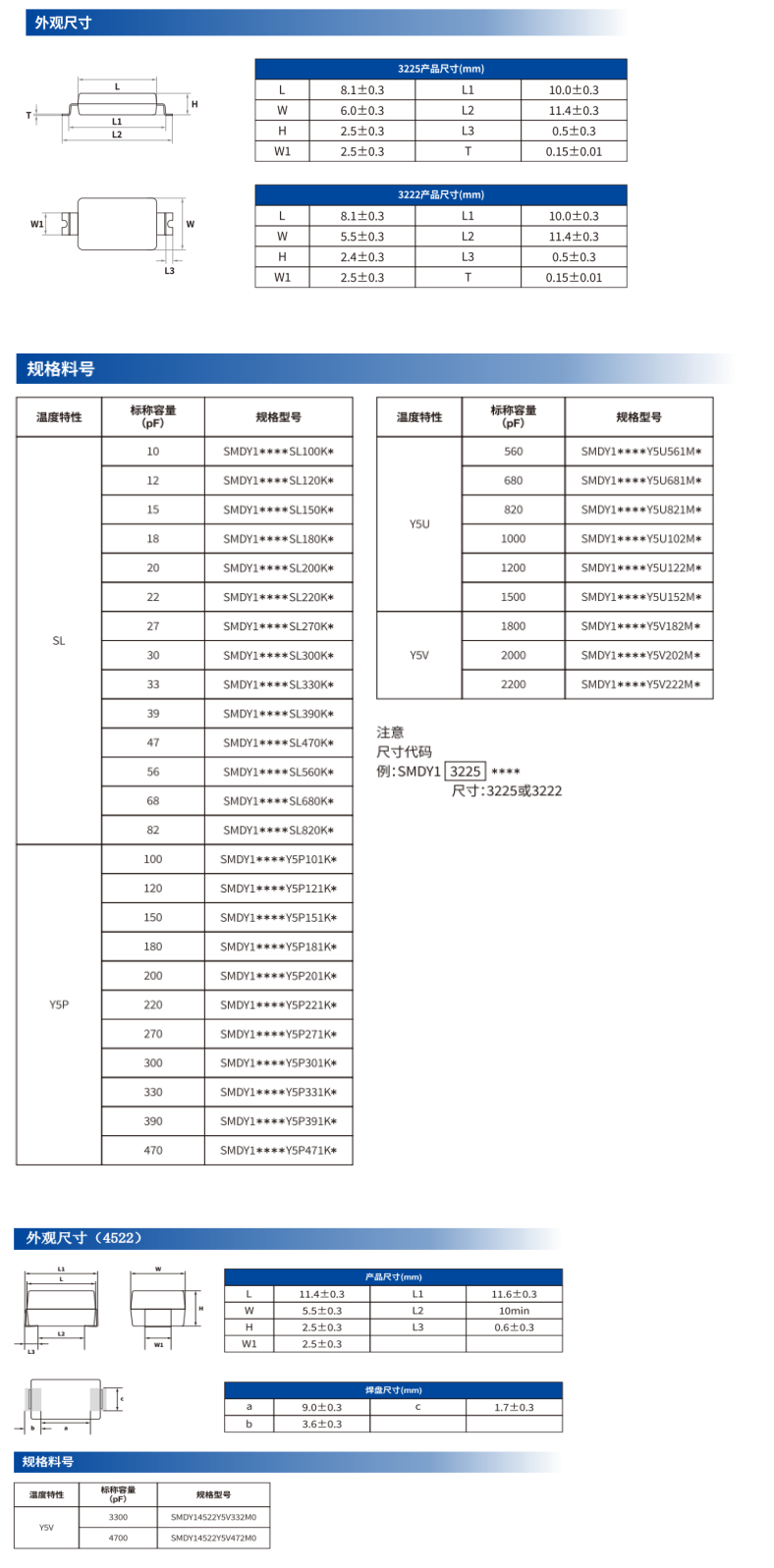
| Parameter | Value in the source image |
|---|---|
| L | 8.1±0.3 |
| W | 6.0±0.3 |
| H | 2.5±0.3 |
| W1 | 2.5±0.3 |
| L1 | 10.0±0.3 |
| L2 | 11.4±0.3 |
| L3 | 0.5±0.3 |
| T | 0.15±0.01 |
| Parameter | Value in the source image |
|---|---|
| L | 8.1±0.3 |
| W | 5.5±0.3 |
| H | 2.4±0.3 |
| W1 | 2.5±0.3 |
| L1 | 10.0±0.3 |
| L2 | 11.4±0.3 |
| L3 | 0.5±0.3 |
| T | 0.15±0.01 |
| Temperature characteristic | Nominal capacitance (pF) | Part number |
|---|---|---|
| SL | 10 | SMDY1****SL100K* |
| SL | 12 | SMDY1****SL120K* |
| SL | 15 | SMDY1****SL150K* |
| SL | 18 | SMDY1****SL180K* |
| SL | 20 | SMDY1****SL200K* |
| SL | 22 | SMDY1****SL220K* |
| SL | 27 | SMDY1****SL270K* |
| SL | 30 | SMDY1****SL300K* |
| SL | 33 | SMDY1****SL330K* |
| SL | 39 | SMDY1****SL390K* |
| SL | 47 | SMDY1****SL470K* |
| SL | 56 | SMDY1****SL560K* |
| SL | 68 | SMDY1****SL680K* |
| SL | 82 | SMDY1****SL820K* |
| Y5P | 100 | SMDY1****Y5P101K* |
| Y5P | 120 | SMDY1****Y5P121K* |
| Y5P | 150 | SMDY1****Y5P151K* |
| Y5P | 180 | SMDY1****Y5P181K* |
| Y5P | 200 | SMDY1****Y5P201K* |
| Y5P | 220 | SMDY1****Y5P221K* |
| Y5P | 270 | SMDY1****Y5P271K* |
| Y5P | 300 | SMDY1****Y5P301K* |
| Y5P | 330 | SMDY1****Y5P331K* |
| Y5P | 390 | SMDY1****Y5P391K* |
| Y5P | 470 | SMDY1****Y5P471K* |
| Y5U | 560 | SMDY1****Y5U561M* |
| Y5U | 680 | SMDY1****Y5U681M* |
| Y5U | 820 | SMDY1****Y5U821M* |
| Y5U | 1000 | SMDY1****Y5U102M* |
| Y5U | 1200 | SMDY1****Y5U122M* |
| Y5U | 1500 | SMDY1****Y5U152M* |
| Y5V | 1800 | SMDY1****Y5V182M* |
| Y5V | 2000 | SMDY1****Y5V202M* |
| Y5V | 2200 | SMDY1****Y5V222M* |
The size code is 3225 or 3222. Asterisks are retained as shown in the source.
| Parameter | Value in the source image |
|---|---|
| L | 11.4±0.3 |
| W | 5.5±0.3 |
| H | 2.5±0.3 |
| W1 | 2.5±0.3 |
| L1 | 11.6±0.3 |
| L2 | 10 min |
| L3 | 0.6±0.3 |
| Parameter | Value in the source image |
|---|---|
| a | 9.0±0.3 |
| b | 3.6±0.3 |
| c | 1.7±0.3 |
| Temperature characteristic | Nominal capacitance (pF) | Part number |
|---|---|---|
| Y5V | 3300 | SMDY14522Y5V332M0 |
| Y5V | 4700 | SMDY14522Y5V472M0 |
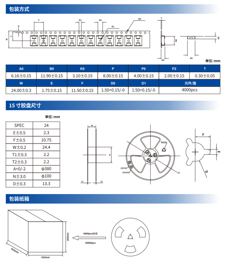
| Parameter | Value in the source image |
|---|---|
| A0 | 6.16±0.15 |
| B0 | 11.90±0.15 |
| K0 | 3.10±0.15 |
| P | 8.00±0.15 |
| P0 | 4.00±0.15 |
| P2 | 2.00±0.15 |
| T | 0.30±0.05 |
| W | 24.00±0.3 |
| E | 1.75±0.15 |
| F | 11.50±0.15 |
| D0 | 1.50 +0.15/−0 |
| D1 | 1.50 +0.15/−0 |
| Components per reel | 4000 pcs |
| Parameter | Value in the source image |
|---|---|
| SPEC | 24 |
| E ±0.5 | 2.3 |
| F ±0.5 | 10.75 |
| W ±0.2 | 24.4 |
| T1 ±0.3 | 2.2 |
| T2 ±0.3 | 2.2 |
| A +0/−2 | Φ380 |
| N ±3.0 | Φ100 |
| D ±0.3 | 13.3 |
| Parameter | Value in the source image |
|---|---|
| Dimensions | 420 × 420 × 160 mm |
| Quantity | 4000 pcs × 5 reels = 20000 pcs |